You can deploy a Secure Firewall threat defense as a default gateway for your network so that the end users can use the threat defense to communicate with a different subnet or to connect to the Internet. This sample chapter from CCNP Security Cisco Secure Firewall and Intrusion Prevention System Official Cert Guide describes the processes to deploy a threat defense in routed mode.
This chapter provides an overview of the following topics:
Routed Mode Essentials: This section describes the characteristics of a firewall in routed mode.
Best Practices for Routed Mode Configuration: This section discusses some of the best practices that you should consider before you place your threat defense into routed firewall mode.
Fulfilling Prerequisites: In this section, you learn the commands to enable routed firewall mode on a threat defense.
Configuration of the Routed Interface: This section demonstrates the steps to configure routed interfaces with static and dynamic IP addresses.
Validation of Interface Configuration: The last section of this chapter provides useful tips to verify the status of routed interfaces and view the connection events.
The objectives of this chapter are to learn about
Deployment of Secure Firewall in routed firewall mode
Verification of threat defense configurations in routed mode
You can deploy a Secure Firewall threat defense as a default gateway for your network so that the end users can use the threat defense to communicate with a different subnet or to connect to the Internet. You can also deploy a threat defense transparently so that it stays invisible to your network hosts. In short, you can deploy a threat defense in two ways: routed mode and transparent mode. This chapter describes the processes to deploy a threat defense in routed mode. Chapter 5, “Firewall Deployment in Transparent Mode,” discusses the transparent mode.
“Do I Know This Already?” Quiz
The “Do I Know This Already?” quiz enables you to assess whether you should read this entire chapter thoroughly or jump to the “Exam Preparation Tasks” section. If you are in doubt about your answers to these questions or your own assessment of your knowledge of the topics, read the entire chapter. Table 4-1 lists the major headings in this chapter and their corresponding “Do I Know This Already?” quiz questions. You can find the answers in Appendix A, “Answers to the ‘Do I Know This Already?’ Quizzes.”
Table 4-1 “Do I Know This Already?” Section-to-Question Mapping
Foundation Topics Section |
Questions |
|---|---|
Routed Mode Essentials |
1 |
Best Practices for Routed Mode Configuration |
2 |
Fulfilling Prerequisites |
3 |
Configuration of the Routed Interface |
4 |
Validation of Interface Configuration |
5, 6 |
1. Which of the following statements is true?
Threat defense in transparent mode cannot be configured by a management center.
You can change the firewall deployment mode by using the management center.
You cannot change the firewall mode until you unregister the threat defense from the management center.
When you change the firewall mode, the threat defense saves the running configurations.
2. Which of the following statements is false?
When configured in Layer 3 mode, each data interface on a threat defense is required to be on a different network.
Backing up a security policy configuration on a threat defense is not necessary because the security policies are defined and stored on the management center.
Changing the firewall mode does not affect the existing configurations on a threat defense.
None of these answers are correct.
3. Which of the following commands is used to configure a threat defense from transparent mode to routed mode?
configure routed
configure firewall routed
configure interface routed
configure transparent disable
4. Which of the following statements is false for IP address configuration?
A threat defense data interface must be configured with a static IP address.
A threat defense can function as a DHCP client as well as a DHCP server.
When you create an address pool for the DHCP server, it must be within the same subnet as the connected interface.
None of these answers are correct.
5. Which of the following commands is used to debug and analyze ping requests?
debug icmp
debug ip icmp
debug icmp trace
debug icmp reply
6. Which of the following commands can be run to determine any interface-related issues?
show interface ip brief
show interface interface_ID
show running-config interface
All of these answers are correct.
Routed Mode Essentials
In routed mode, a threat defense acts like a Layer 3 hop. Each interface on a threat defense can be connected to a different subnet, and the threat defense can act as the default gateway for that subnet. The threat defense can also route traffic between different subnets, like a Layer 3 router.
Figure 4-1 shows how a host interacts with a threat defense as its next Layer 3 hop. In routed mode, each threat defense interface connects to a unique subnet.
)
FIGURE 4-1 Communication of a Host with a Threat Defense in Routed Mode
Best Practices for Routed Mode Configuration
If you want to deploy a threat defense in routed mode, consider the following suggestions:
Do not configure the diagnostic interface with an IP address. This simplifies the network design and reduces configuration overhead. When a diagnostic interface is configured with an IP address, a threat defense treats it like a data interface. When configured in Layer 3 mode, each data interface on a threat defense is required to be on a different network. Therefore, the diagnostic interface (which must be on the same subnet as the logical management interface, br1) and the inside interface must be on two different subnets. To transfer traffic between two different subnetworks, the routing service is required.
Changing the firewall mode wipes out any existing configurations on a threat defense. Therefore, before you change the firewall mode from transparent to routed or vice versa, take note of your threat defense settings for future reference, in case you want to revert the threat defense to the prior state. To view the current threat defense configuration, run the show running-config command in the CLI.
If you just want to change the firewall mode of a threat defense, backing up your security policy configuration is not necessary because the next-generation security policies are defined and stored on the management center. After you configure the security policies, the management center allows you to deploy the same policies to one or more threat defense devices.
Fulfilling Prerequisites
Do you remember the last part of the threat defense installation and initialization process? During the initialization, the threat defense prompts to confirm the firewall mode, and you can select between routed mode and transparent mode (see Example 4-1). If you selected routed mode during the system initialization, you can skip this section and read the section “Configuration of the Routed Interface.”
Example 4-1 Configuring the Firewall Mode During the Initialization
<Output Omitted>
.
.
Manage the device locally? (yes/no) [yes]: no
 Configure firewall mode? (routed/transparent) [routed]:
Configuring firewall mode ...
Update policy deployment information
   - add device configuration
   - add network discovery
   - add system policy
.
.
<Output Omitted>
If you selected transparent mode during the system initialization and now you want to reconfigure your threat defense to routed mode, you must unregister the threat defense from the management center. You cannot change the firewall mode when a manager is configured. To verify whether a threat defense is currently registered with the management center, run the show managers command at the threat defense CLI.
Example 4-2 shows that the threat defense is currently registered with a management center with IP address 10.1.1.2.
Example 4-2 Threat Defense Is Currently Registered with a Management Center
> show managers
Type         : Manager
Host         : 10.1.1.2
Registration : Completed
>
If your threat defense is currently in transparent mode and registered with a management center, you can unregister it by using the management center web interface. To delete registration, go to Devices > Device Management, click the three dots next to threat defense name, and select Delete (see Figure 4-2).
)
FIGURE 4-2 Deleting the Registration of a Threat Defense in Transparent Mode
Example 4-3 shows confirmation that the threat defense is neither registered with the management center nor enabled with its local device manager service.
Example 4-3 Threat Defense Is Not Managed by a Management Center or Built-in Local Manager
> show managers
No managers configured.
>
Enabling the Routed Firewall Mode
You can change the firewall mode of a threat defense if it is currently not registered with a management center. To configure a threat defense with routed mode, log in to the threat defense CLI and run the configure firewall routed command (see Example 4-4).
Example 4-4 Configuring the Routed Mode
> configure firewall routed

This will destroy the current interface configurations, are you sure that you want
to proceed? [y/N] y
The firewall mode was changed successfully.
After configuring the threat defense to the desired mode, you can determine the status from the CLI. Example 4-5 confirms that the threat defense is in routed mode.
Example 4-5 Verifying the Firewall Deployment Mode
> show firewall
Firewall mode: Router
>
Alternatively, upon a successful registration, the management center GUI also displays the current firewall deployment mode. You can view it by navigating to Devices > Device Management. Figure 4-3 indicates that the threat defense is configured in routed mode.
)
FIGURE 4-3 Threat Defense Is Deployed in Routed Mode
Configuration of the Routed Interface
In threat defense, you can configure a data interface with a static IP address. A threat defense can also operate as a DHCP client and obtain an IP address from a DHCP server. Furthermore, you can enable the DHCP service on a threat defense and configure it to assign IP addresses dynamically to its hosts.
Configuring Interfaces with Static IP Addresses
To configure a routed interface with a static IP address, follow these steps:
Step 1. Navigate to Devices > Device Management. A list of the managed devices appears.
Step 2. Click the pencil icon that is next to the threat defense name you want to configure. The device management editor page appears, showing all the interfaces of threat defense on the Interfaces tab (see Figure 4-4).
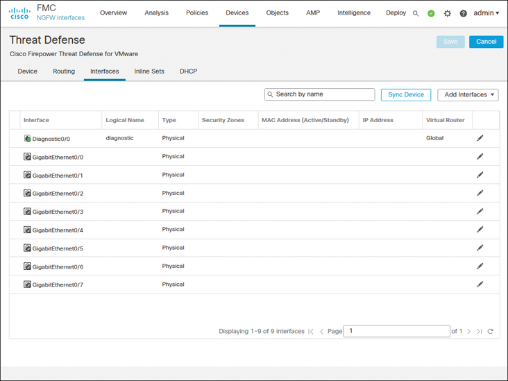
FIGURE 4-4 Interfaces Tab of the Virtual Threat Device
Depending on the threat defense platform you run, you may come across different types of interfaces and model-specific options. For example, threat defense model 1010 comes with an Ethernet type interface with built-in switch ports, as shown in Figure 4-5. To configure this model in routed mode, you need to disable access mode switch ports.
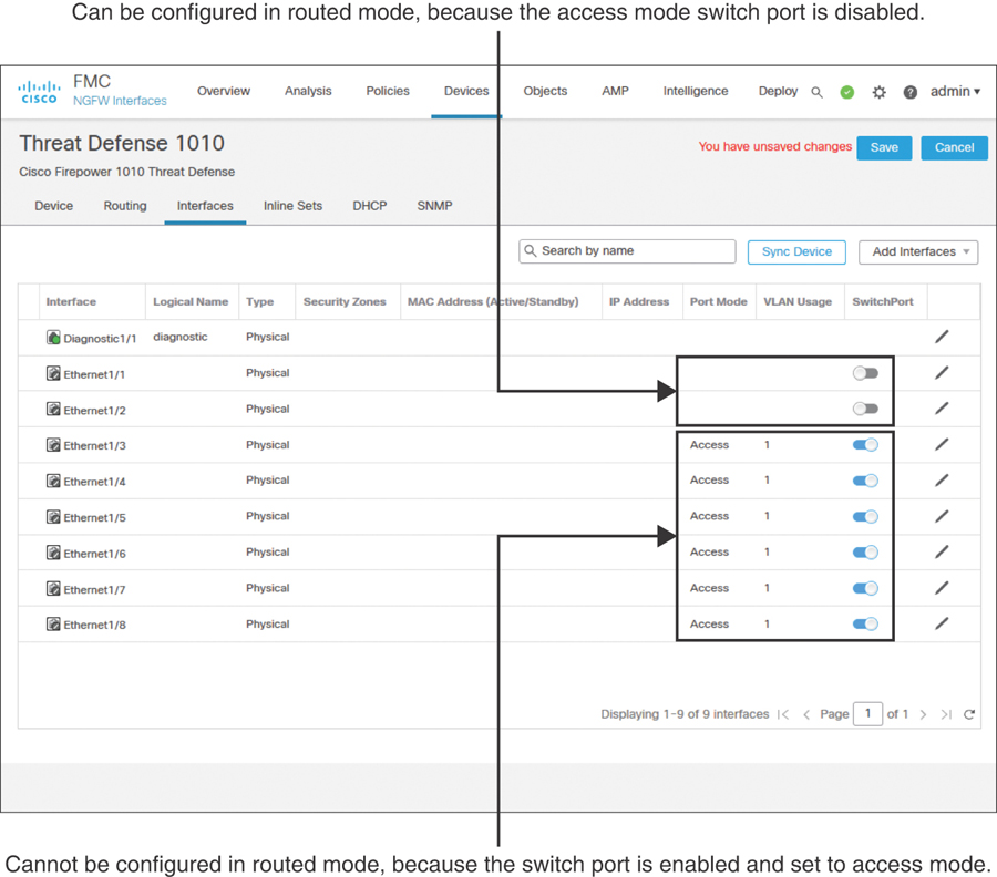
FIGURE 4-5 Interfaces Tab of Threat Defense Model 1010 Shows Switch Port Modes
Step 3. On the Interfaces tab, click the pencil icons next to GigabitEthernet0/0 and GigabitEthernet0/1 to configure these interfaces for the inside and outside networks, respectively. Use the settings shown in Table 4-2 to configure these two interfaces.
Table 4-2 Settings for Ingress and Egress Interfaces
GigabitEthernet0/0
GigabitEthernet0/1
Interface name
INSIDE_INTERFACE
OUTSIDE_INTERFACE
Security zone (optional)
INSIDE_ZONE
OUTSIDE_ZONE
IP address
192.168.1.1/24
172.16.1.1/24
To enable an interface, you must give it a name; this is a requirement. However, configuring a security zone is an optional step. Here, in the Edit Physical Interface window, you can create a security zone and associate it with an interface on the fly. In future, you could use the Objects > Object Management > Interface page to manage the security zones.
Figure 4-6 shows the general settings for GigabitEthernet0/0; for example, it is named INSIDE_INTERFACE. Make sure to enable an interface using the Enabled check box.
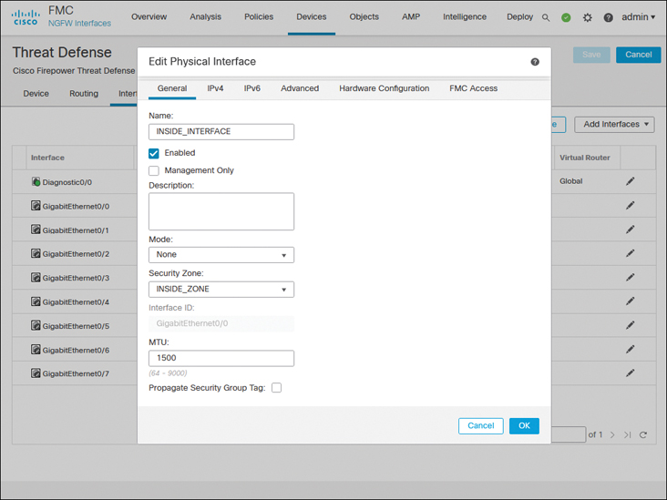
FIGURE 4-6 General Configurations of the Inside Interface
Figure 4-7 shows the manual assignment of a static IP address to the GigabitEthernet0/0 interface.
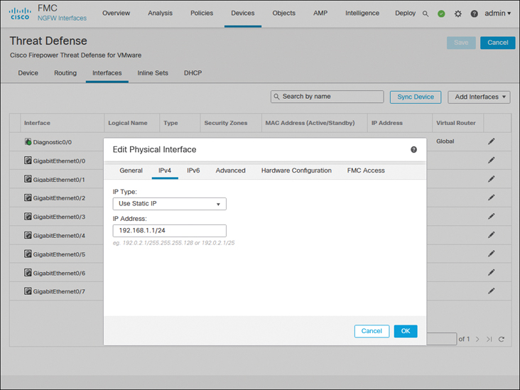
FIGURE 4-7 Static IP Address on the Inside Interface GigabitEthernet0/0
Step 4. Repeat the preceding steps for GigabitEthernet0/1 to enable it for the outside network. When you’re finished, click the Save button to save the changes.
Figure 4-8 shows the configurations of ingress and egress routed interfaces.
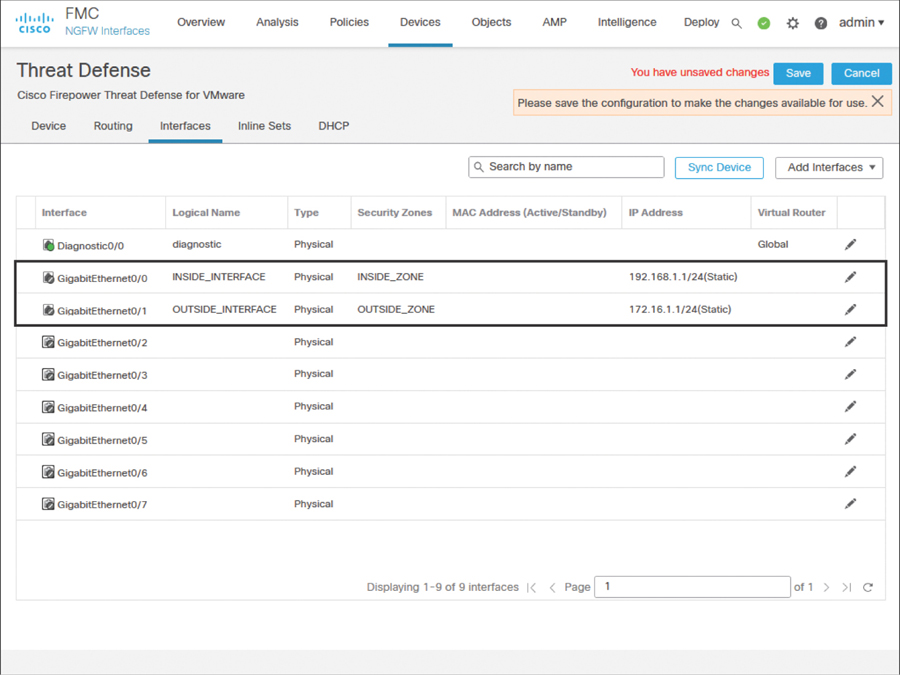
FIGURE 4-8 Inside and Outside Interface Configurations
Step 5. After the configuration is saved, navigate to Deploy > Deployment. Select the threat defense where you want to apply the changes and click the Deploy button to apply the configurations (see Figure 4-9).

FIGURE 4-9 Threat Defense Configuration Deployment
)
)
)
)
)
)
Configuring Interfaces with Automatic IP Addresses
A threat defense can function as a DHCP client as well as a DHCP server. For example, if you deploy a threat defense between the outside interface and an Internet service provider (ISP), the device can obtain an IP address dynamically for its outside interface from the ISP router. Simultaneously, a threat defense can act as a DHCP server and provide IPv4 addresses dynamically to the hosts it inspects through its inside interface. Configuring a threat defense as a DHCP server is an optional choice; it does not influence the deep packet inspection capability.
Figure 4-10 illustrates two scenarios: The inside network obtains an IP address from the DHCP service running on a threat defense, while the outside interface of the threat defense gets an IP address from a service provider.
)
FIGURE 4-10 A Threat Defense as a DHCP Server and a DHCP Client
Enabling an interface to obtain an IP address from a DHCP server is a straightforward process. For example, during the outside interface configuration, when you assign a static IP address to the interface, you simply select Use DHCP from the drop-down instead of selecting the Use Static IP option. That’s it. When this interface configuration is deployed, the outside interface attempts to obtain the IP address from an external DHCP server or the ISP router. See Figure 4-11 to find the Use DHCP option.
)
FIGURE 4-11 Interface Configuration to Run a Threat Defense as a DHCP Client
However, if you want the threat defense to provide IP addresses dynamically to its connected hosts, you need to enable DHCP services on it. The following steps describe how to configure a threat defense with DHCP services and allow its inside interface to provide IP addresses to its connected host computers:
Step 1. Go to Devices > Device Management and click the pencil icon to edit the threat defense configuration.
Step 2. Assign the static IP address 192.168.1.1 on GigabitEthernet0/0—the inside interface of the threat defense. Your end users (DHCP clients) will be using this IP address as their default gateway. (Figure 4-10 illustrates the purpose of the inside interface.)
Step 3. On the device editor page, go to the DHCP tab. By default, the DHCP Server page appears.
Step 4. Click the Add button on the Server tab (located near the bottom part of the DHCP Server page). The Add Server window appears.
Step 5. In the Add Server window, select the inside interface from the drop-down list because it will be offering IP addresses to the inside network.
Step 6. Create an address pool for the DHCP server. Remember that the addresses in the pool must be within the same subnet as the connected interface. For example, if you assign 192.168.1.1/24 to the inside interface, the DHCP address pool should be between 192.168.1.2 and 192.168.1.254.
Figure 4-12 shows that a DHCP server is enabled on the threat defense’s inside interface with the address pool 192.168.1.2 to 192.168.1.10.
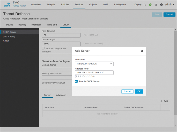
FIGURE 4-12 DHCP Server Configurations on a Threat Defense
Step 7. Select the Enable DHCP Server check box to enable the service and click OK. You return to the device editor page.
Step 8. Optionally, through the DHCP service, a threat defense can transfer any DNS-related information to your DHCP clients. The DHCP Server page allows you to enter domain names and DNS addresses manually. Alternatively, you can select the Auto-Configuration check box to let the threat defense obtain any DNS information automatically from a DHCP client connected to a predefined interface.
Step 9. Click the Save button to save the configurations. To deploy the configurations to your threat defense, go to Deploy > Deployment, select the threat defense you wish to configure, and click the Deploy button (shown previously in Figure 4-9).
)
Validation of Interface Configuration
After the configurations are deployed to the threat defense, the hosts between the inside network and outside network should be able to communicate successfully. To test connectivity, you can simply run an ICMP ping test between the inside and outside hosts. If the hosts are running any services (such as web or Secure Shell), you can also use them to verify connectivity.
In a brand-new deployment, the management center does not display connection events. If you would like to use your management center to validate any connection attempts through your threat defense, you need to enable logging in the access control policy. By default, a new access control policy does not come with any customizable access control rule. Because we describe the operation of an access control rule in later chapters, for now, you can add a simple access control rule to allow the traffic and enable logging within that rule (see Figure 4-13). Alternatively, in an access control policy without any rule, you can simply enable logging in the default action (see Figure 4-14), which can also trigger connection events.
)
FIGURE 4-13 Enabling Logging Within an Access Control Rule
)
FIGURE 4-14 Enabling Logging in an Access Control Policy as a Default Action
If you deployed the access control policy with logging functionality enabled, you can now view events for any associated connections by navigating to Analysis > Connections > Events of your management center.
Figure 4-15 exhibits connection attempts from an inside host (IP: 192.168.1.2) to an outside host (IP: 172.168.1.2) over ICMP, SSH, and HTTPS protocols.
)
FIGURE 4-15 Table View of Connection Events Between Inside and Outside Hosts
While you run ICMP traffic, you can view the details of how the system is processing the ICMP packets by using the debug command.
Example 4-6 shows ICMP requests and replies exchanged between two computers located in the inside and outside networks.
Example 4-6 Debugging ICMP Traffic in a Threat Defense
> debug icmp trace
debug icmp trace enabled at level 1
>
ICMP echo request from INSIDE_INTERFACE:192.168.1.2 to OUTSIDE_INTERFACE:172.16.1.100
ID=4101 seq=1 len=56
ICMP echo reply from OUTSIDE_INTERFACE:172.16.1.100 to INSIDE_INTERFACE:192.168.1.2
ID=4101 seq=1 len=56
ICMP echo request from INSIDE_INTERFACE:192.168.1.2 to OUTSIDE_INTERFACE:172.16.1.100
ID=4101 seq=2 len=56
ICMP echo reply from OUTSIDE_INTERFACE:172.16.1.100 to INSIDE_INTERFACE:192.168.1.2
ID=4101 seq=2 len=56
.
.
<Output Omitted>

> undebug all
>
If the ping test fails, you need to determine the status of the interfaces. You can run the following commands on the threat defense to determine the interface status and to verify the configurations you applied from the management center to the threat defense. Command outputs are slightly different depending on the configuration method (static versus dynamic).
show ip
show interface ip brief
show interface interface_ID
show running-config interface
Example 4-7 shows output of the show ip command. You can view the mapping between the interface, logical name, and IP address in this output. You cannot, however, view the current status in the output.
Example 4-7 Output of the show ip Command
> show ip
System IP Addresses:
Interface            Name                IP address    Subnet mask    Method
GigabitEthernet0/0   INSIDE_INTERFACE    192.168.1.1   255.255.255.0  CONFIG
GigabitEthernet0/1   OUTSIDE_INTERFACE   172.16.1.1    255.255.255.0  CONFIG
Current IP Addresses:
Interface            Name                IP address    Subnet mask    Method
GigabitEthernet0/0   INSIDE_INTERFACE    192.168.1.1   255.255.255.0  CONFIG
GigabitEthernet0/1   OUTSIDE_INTERFACE   172.16.1.1    255.255.255.0  CONFIG
>
Example 4-8 confirms that both the GigabitEthernet0/0 and GigabitEthernet0/1 interfaces are up and configured manually (using static IP addresses). The show interface ip brief command provides an overview, including the current status, of each of the interfaces.
Example 4-8 Overview of the Interface Status
> show interface ip brief
Interface               IP-Address     OK? Method Status            Protocol
GigabitEthernet0/0      192.168.1.1    YES CONFIG up                    up
GigabitEthernet0/1      172.16.1.1     YES CONFIG up                    up
GigabitEthernet0/2      unassigned     YES unset  administratively down up
GigabitEthernet0/3      unassigned     YES unset  administratively down up
GigabitEthernet0/4      unassigned     YES unset  administratively down up
GigabitEthernet0/5      unassigned     YES unset  administratively down up
GigabitEthernet0/6      unassigned     YES unset  administratively down up
GigabitEthernet0/7      unassigned     YES unset  administratively down up
Internal-Control0/0     127.0.1.1      YES unset  up                    up
Internal-Control0/1     unassigned     YES unset  up                    up
Internal-Data0/0        unassigned     YES unset  down                  up
Internal-Data0/0        unassigned     YES unset  up                    up
Internal-Data0/1        169.254.1.1    YES unset  up                    up
Internal-Data0/2        unassigned     YES unset  up                    up
Management0/0           unassigned     YES unset  up                    up
>
Example 4-9 shows detailed statistics of the GigabitEthernet0/0 interface. By using the show interface interface_ID command, you can determine any errors and drops that may have occurred on an interface.
Example 4-9 Detailed Statistics of Packets in the Interface Level
> show interface GigabitEthernet 0/0
Interface GigabitEthernet0/0 "INSIDE_INTERFACE", is up, line protocol is up
  Hardware is net_vmxnet3, BW 10000 Mbps, DLY 10 usec
        Auto-Duplex(Full-duplex), Auto-Speed(10000 Mbps)
        Input flow control is unsupported, output flow control is unsupported
        MAC address 000a.000b.abcd, MTU 1500
        IP address 192.168.1.1, subnet mask 255.255.255.0
        277 packets input, 60997 bytes, 0 no buffer
        Received 0 broadcasts, 0 runts, 0 giants
        0 input errors, 0 CRC, 0 frame, 0 overrun, 0 ignored, 0 abort
        0 pause input, 0 resume input
        0 L2 decode drops
        215 packets output, 77346 bytes, 0 underruns
        0 pause output, 0 resume output
        0 output errors, 0 collisions, 0 interface resets
        0 late collisions, 0 deferred
        0 input reset drops, 0 output reset drops
        input queue (blocks free curr/low): hardware (0/0)
        output queue (blocks free curr/low): hardware (0/0)
  Traffic Statistics for "INSIDE_INTERFACE":
        277 packets input, 57079 bytes
        215 packets output, 74336 bytes
        7 packets dropped
      1 minute input rate 0 pkts/sec,  0 bytes/sec
      1 minute output rate 0 pkts/sec,  0 bytes/sec
      1 minute drop rate, 0 pkts/sec
      5 minute input rate 0 pkts/sec,  0 bytes/sec
      5 minute output rate 0 pkts/sec,  0 bytes/sec
      5 minute drop rate, 0 pkts/sec
>
Example 4-10 displays the interface configurations from the CLI. You can find all the settings you configured on the management center and applied to the threat defense.
Example 4-10 Running Configurations of GigabitEthernet0/0 and GigabitEthernet0/1
> show running-config interface
!
interface GigabitEthernet0/0
 nameif INSIDE_INTERFACE
 cts manual
  propagate sgt preserve-untag
  policy static sgt disabled trusted
 security-level 0
 ip address 192.168.1.1 255.255.255.0
!
interface GigabitEthernet0/1
 nameif OUTSIDE_INTERFACE
 cts manual
  propagate sgt preserve-untag
  policy static sgt disabled trusted
 security-level 0
 ip address 172.16.1.1 255.255.255.0
!
interface GigabitEthernet0/2
 shutdown
 no nameif
 no security-level
 no ip address
.
.
<Output Omitted for Brevity>
.
.
>
If the threat defense does not offer an IP address to its DHCP clients, or if the threat defense cannot obtain an IP address from any external DHCP server, you can debug any DHCP transactions to and from the DHCP server.
Example 4-11 proves that the threat defense has dynamically assigned the IP address 192.168.1.2 to a host with the MAC address C4:2C:03:3C:98:A8. This IP address is the first address from the DHCP address pool 192.168.1.2 to 192.168.1.10.
Example 4-11 Verifying the IP Address Assignment from a DHCP Address Pool
> show dhcpd binding

IP address   Client Identifier   Lease expiration    Type
 192.168.1.2     c42c.033c.98a8       3580 seconds  Automatic
>
If you do not see any DHCP binding, you can debug the DHCP packets on the threat defense.
Example 4-12 demonstrates the process of a DHCP server assigning an IP address. In the debug output, you can analyze the four major stages of the DHCP protocol: Discovery, Offer, Request, and Acknowledgment (DORA).
Example 4-12 Exchange of DHCP Packets Between a Threat Defense and a DHCP Server
> debug dhcpd packet
debug dhcpd packet enabled at level 1
>

DHCPD/RA: Server msg received, fip=ANY, fport=0 on INSIDE_INTERFACE interface
DHCPD: DHCPDISCOVER received from client c42c.033c.98a8 on interface
INSIDE_INTERFACE.
DHCPD: send ping pkt to 192.168.1.2
DHCPD: ping got no response for ip: 192.168.1.2
DHCPD: Add binding 192.168.1.2 to radix tree
DHCPD/RA: Binding successfully added to hash table
DHCPD: Sending DHCPOFFER to client c42c.033c.98a8 (192.168.1.2).

DHCPD: Total # of raw options copied to outgoing DHCP message is 0.
DHCPD/RA: creating ARP entry (192.168.1.2, c42c.033c.98a8).
DHCPD: unicasting BOOTREPLY to client c42c.033c.98a8(192.168.1.2).
DHCPD/RA: Server msg received, fip=ANY, fport=0 on INSIDE_INTERFACE interface
DHCPD: DHCPREQUEST received from client c42c.033c.98a8.
DHCPD: Extracting client address from the message
DHCPD: State = DHCPS_REBOOTING
DHCPD: State = DHCPS_REQUESTING
DHCPD: Client c42c.033c.98a8 specified it’s address 192.168.1.2
DHCPD: Client is on the correct network
DHCPD: Client accepted our offer
DHCPD: Client and server agree on address 192.168.1.2
DHCPD: Renewing client c42c.033c.98a8 lease
DHCPD: Client lease can be renewed
DHCPD: Sending DHCPACK to client c42c.033c.98a8 (192.168.1.2).
DHCPD: Total # of raw options copied to outgoing DHCP message is 0.
DHCPD/RA: creating ARP entry (192.168.1.2, c42c.033c.98a8).
DHCPD: unicasting BOOTREPLY to client c42c.033c.98a8(192.168.1.2).

>
Summary
This chapter explains how to configure a threat defense in routed mode. It describes the steps to configure the routed interfaces of a threat defense with static IP addresses as well as dynamic IP addresses. In addition, this chapter discusses various command-line tools you can use to determine any potential interface-related issues.
Exam Preparation Tasks
As mentioned in the section “How to Use This Book” in the Introduction, you have a couple of choices for exam preparation: the exercises here, Chapter 22, “Final Preparation,” and the exam simulation questions in the Pearson Test Prep practice test software.
Review All Key Topics
Review the most important topics in this chapter, noted with the Key Topic icon in the outer margin of the page. Table 4-3 lists a reference of these key topics and the page numbers on which each is found.
Table 4-3 Key Topics for Chapter 4
Key Topic Element |
Description |
Page |
|---|---|---|
Paragraph |
Routed firewall mode |
72 |
Paragraph |
DHCP client vs. DHCP server |
80 |
Define Key Terms
Define the following key terms from this chapter, and check your answers in the Glossary:
routed mode
switch port
DHCP service
connection event