In this sample chapter from Implementing Cisco HyperFlex Solutions, you will review the HyperFlex HX Data Platform disaster recovery feature and configuration steps needed to enable replication between two HyperFlex clusters.
The HyperFlex HX Data Platform disaster recovery feature allows you to protect virtual machines (VMs) by setting up replication so that protected virtual machines running on one cluster replicate to the other cluster in a pair of network-connected clusters and vice versa. The two paired clusters typically are located at a distance from each other, with each cluster serving as the disaster recovery site for virtual machines running on the other cluster. Once protection has been set up on a VM, the HX Data Platform periodically takes a replication snapshot of the running VM on the local cluster and replicates (copies) the snapshot to the paired remote cluster. In the event of a disaster at the local cluster, you can use the most recently replicated snapshot of each protected VM to recover and run the VM at the remote cluster. Each cluster that serves as a disaster recovery site for another cluster must be sized with adequate spare resources so that, in the event of a disaster, it can run the newly recovered virtual machines in addition to its normal workload.
This chapter describes the HyperFlex HX Data Platform disaster recovery feature and describes the configuration steps needed to enable replication between two HyperFlex clusters. It also covers the available backup solutions that can be integrated with HyperFlex HX Data Platform.
Data Protection
There are several schools of thought on data protection. Some people believe that high availability and durability are part of data protection. Some say that stretch clusters are also part of data protection. However, two very basic parameters or variables allow you to determine the data protection solution you should use: recovery time objective (RTO) and recovery point objective (RPO).
RTO essentially refers to how much time it takes for a service or a virtual machine to come up after a disaster or failure has occurred. RPO indicates how much data loss someone is ready to bear while waiting for services to come up.
HyperFlex offers the following protection options, listed here from low RTO/RPO level to high RTP/RPO level:
Local resiliency (high availability and durability):
Two (RF-2) or three (RF-3) copies of VM data
Data stripped and distributed across all local nodes
Redundant network paths
An HA-aware hypervisor
Zero RPO and zero or very low RTO
Site-level resiliency (stretch clusters):
Four copies (RF 2+2) of VM data
Protection against local failures and site failures
Protection against “split brains”
VM data mirrored across sites
An HA-aware hypervisor
Zero RPO and zero or very low RTO
Snapshots (VM-centric snapshots):
VM-centric instant, space optimized
Redirect-on-write snapshots
Scheduled with a retention policy
Quiesced and crash consistent
Rapid provisioning using ReadyClones
“Now”/hourly/daily/weekly RPO and RTO in minutes
Replication and disaster recovery (VM-centric replication and disaster recovery):
VM-centric replication
Periodic asynchronous replication to remote site (WAN distance)
Snapshot based
Failover, fast failback, and test recovery
Minutes/hourly/daily RPO and RTO in minutes
Backup and Archive (third-party backup vendor integration):
Fully verified Cisco Validated Design (CVD) on UCS infrastructure
Integrated with HyperFlex native snapshots
Accelerated transfers and low backup window
Hourly/daily RPO and RTO in minutes/hours
Replication Overview
HyperFlex 2.5 introduced new data protection features, including snapshot-based VM-level replication between two HyperFlex clusters. Replication can be used to migrate or recover a single VM in the secondary HX cluster, coordinate or recover groups of VMs, or recover all VMs as part of a disaster recovery scenario. In order to start using replication, you must install two HyperFlex clusters and ensure network connectivity between them. The clusters can be extended clusters, and it is possible to replicate between hybrid and all flash clusters. The clusters are allowed to use self-encrypting disks or standard disks in either location, both of them, or neither of them; there is no restriction in that respect. To avoid complications with duplicate VM IDs, recommended practice dictates that the two replicating HyperFlex clusters be managed by two different VMware vCenter servers. Figure 6-1 shows the logical network topology used for replication.
)
Figure 6-1 Replication Logical Network Topology
Port Requirements for Replication
The firewall ports listed in Table 6-1 need to be open when configuring native HX asynchronous cluster-to-cluster replication. If any of these ports are not open, the storage controller virtual machines (SCVMs) cannot communicate using the specific service for which the ports are closed. Closed ports also prevent the proper functionality of the replication feature.
Table 6-1 Firewall Ports Required to Be Open for Replication
Port Number |
Service/Protocol |
Source |
Port Destinations |
Essential Information |
9338 |
Data Services Manager |
Each CVM node |
Each CVM |
Bidirectional, including cluster management IP addresses |
3049 |
Replication for CVM/TCP |
Each CVM node |
Each CVM |
Bidirectional, including cluster management IP addresses |
4049 |
Cluster Map/TCP |
Each CVM node |
Each CVM node |
Bidirectional, including cluster management IP addresses |
4059 |
NR NFS/TCP |
Each CVM node |
Each CVM node |
Bidirectional, including cluster management IP addresses |
9098 |
Replication Service |
Each CVM node |
Each CVM node |
Bidirectional, including cluster management IP addresses |
8889 |
NR Master for Coordination/TCP |
Each CVM node |
Each CVM node |
Bidirectional, including cluster management IP addresses |
9350 |
Hypervisor Service/TCP |
Each CVM node |
Each CVM node |
Bidirectional, including cluster management IP addresses |
Replication Considerations
When applying replication in HyperFlex, consider the following:
Administrator: All replication and recovery tasks, excluding monitoring, can only be performed with administrator privileges on the local cluster. For tasks involving a remote cluster, both the local and remote user must have administrator privileges and should be configured with the vCenter SSO on their respective clusters.
Storage space: Ensure that there is sufficient space on the remote cluster to support the replication schedule. The protected virtual machines are replicated (copied) to the remote cluster at every scheduled interval. Although storage capacity methods (deduplication and compression) are applied, each replicated virtual machine will consume some storage space.
Not having sufficient storage space on the remote cluster can cause the remote cluster to reach capacity usage maximums. If there are errors reporting out-of-space errors, all replication schedules must be paused until the space is appropriately adjusted on the HX cluster. Always ensure that the cluster capacity consumption is below the space utilization warning threshold.
Supported clusters: Replication is supported between the following HyperFlex clusters:
1:1 replication between HX clusters running under fabric interconnects.
1:1 replication between all flash and hybrid HX cluster running under fabric interconnects.
1:1 replication between a 3-node or 4-node HX Edge cluster and another 3-node or 4-node HX edge cluster.
1:1 replication between all flash 3-node and 4-node edge and hybrid 3-node and 4-node HX edge clusters.
1:1 replication between a 3-node or 4-node HX edge cluster and an HX cluster running under fabric interconnects.
Recovery Considerations
When configuring recovery in HyperFlex, consider the following:
Rebooting nodes: Do not reboot any nodes in an HX cluster during any restore, replication, or recovery operation.
Thin provision: Protected virtual machines are recovered with thin provisioned disks, regardless of how disks were specified in the originally protected virtual machine.
Protection group limitations: The maximum number of VMs allowed in a protection group is 32. Do not add VMs with ISOs or floppies to protection groups.
Non-HX datastores: If you have protected a VM with storage on a non-HX data-store, periodic replication will fail. You can either unprotect this VM or remove its non-HX storage. Do not move protected VMs from HX datastores to non-HX data-stores. If a VM is moved to a non-HX datastore through storage vMotion, unprotect the VM and then reapply the protection.
Protection and recovery of virtual machines with snapshots: There are several options:
VM with no snapshots: When replication is enabled, the entire content of the VM is replicated.
VM with VMware Redo-log snapshots: When replication is enabled, the entire content, including the snapshot data, is replicated. When a VM with redo-log snapshots is recovered, all previous snapshots are preserved.
VM with HyperFlex snapshots: When replication is enabled, only the latest data is replicated, and the snapshot data is not replicated. When the VM is recovered, previous snapshots are not preserved.
Data protection and disaster recovery (DR) snapshots: These snapshots are stored on the same datastore as the protected VMs. Manual deletion of these snapshots is not supported. Deleting the snapshot directories would compromise HX data protection and disaster recovery.
Replication Networking Overview
The HyperFlex clusters that will replicate must have TCP/IP connectivity between them, and additional IP addresses must be provided to an internal IP address pool that the HX SCVMs will use. The minimum number of IP addresses required is the number of nodes in the cluster plus 1 additional address. More addresses than are currently needed can be placed into the pool to allow for future growth of the HX cluster. An existing VLAN ID and subnet can be used, although it is more typical to configure a specific VLAN and subnet to carry replication traffic that will traverse the campus or WAN links between the two clusters. The VLANs that will be used for replication traffic must already be trunked to the Cisco UCS fabric interconnects from the Northbound network by the upstream switches, and this configuration step must be done manually prior to beginning the HyperFlex Connect configuration. The bandwidth usage of the replication traffic can be set to a limit to avoid saturation of the interconnecting network links, or it may be left unlimited, in which case the maximum network bandwidth is set as the total available to the network. The bandwidth consumption will be directly affected by the number of VMs being protected and the frequency of their replication. The set bandwidth limit must not exceed the physical bandwidth, and it must be the same on both sites of the disaster recovery environment. The allowed low bandwidth is 10 Mbps, and the maximum latency supported with 10 Mbps is 75 ms.
The interconnection between the two clusters at the two sites can be done in several ways. In most cases, the uplinks from the HX clusters carry all the needed VLAN IDs on the same set of interfaces, including HX management, vMotion, storage traffic, guest VM traffic, and the replication traffic. In some cases, it is desired that the replication traffic traverse a set of independent uplinks, which is referred to as a split L2 topology. However, due to a technical limitation, the configuration of replication networking cannot accommodate a split L2 configuration. Specifically, a single Cisco UCS vNIC cannot carry multiple VLANs that traverse multiple uplink groups. Because the default configuration uses vmnic0 and vmnic1 to carry HX management traffic and replication traffic, both of those VLANs must arrive to UCS across a single set of uplinks. The replication subnets and VLANs used in the two sites can be different routed subnets, or they can be a single subnet if the WAN is using other technologies, such as Overlay Transport Virtualization (OTV). Replication traffic originates and terminates on the SCVMs running on each HX host.
Figure 6-2 shows the network topology of a two-HX cluster.
)
Figure 6-2 Replication Network
Replication Network Considerations
A replication network must be established between clusters that are expected to use replication for data protection. This replication network is created to isolate inter-cluster replication traffic from other traffic within each cluster and site.
The following is a list of considerations when configuring replication networks and pairing:
To support efficient replication, all M nodes of Cluster A have to communicate with all N nodes of Cluster B, as illustrated in Figure 6-3 in the next section.
To enable replication traffic between clusters to cross the site boundary and traverse the Internet, each node on Cluster A should be able to communicate with each node on Cluster B across the site boundary and the Internet.
The replication traffic must be isolated from other traffic within the cluster and the data center.
Creating this isolated replication network for intercluster traffic involves creating a replication network on each cluster and then pairing clusters to associate the clusters and establish M*N connectivity between the clusters.
IP addresses, subnet, VLAN, and gateway are associated with each replication network of each cluster. You must configure the corporate firewall and routers on both sites to allow communication between the clusters and the sites on TCP ports 9338, 3049, 9098, 4049, and 4059.
)
Figure 6-3 M*N Cluster Connectivity
M*N Connectivity Between Clusters
Figure 6-3 shows the connectivity between two clusters: a primary cluster with four nodes and a secondary cluster with four nodes.
Configuring a Replication Network in HX Connect
A replication network can be configured only once. Once a replication network is configured, you can edit the available IP addresses and the networking bandwidth. Here’s how you configure the network:
Step 1. Log in to HX Connect as administrator by entering the username and password, as shown in Figure 6-4, and clicking Login.
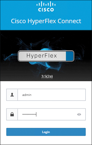
Figure 6-4 HX Connect Login Page
Step 2. In the HyperFlex Connect screen that appears, select the Replication page and then click Replication Configuration > Configure Network (see Figure 6-5).
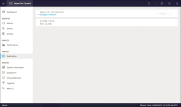
Figure 6-5 Replication Network Configuration
Step 3. In the Configure Replication Network dialog box, on the VLAN Configuration tab, enter the network information:
Select an existing VLAN: Click this radio button to add an existing VLAN(see Figure 6-6).
Create a new VLAN: If you select this radio button, the following fields become available (see Figure 6-7):
VLAN ID: A VLAN that is different from the HX Data Platform management traffic network and data traffic network
VLAN Name: The name of the VLAN
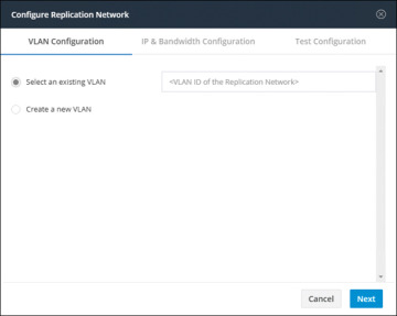
Figure 6-6 Existing VLAN Assignment for Replication Network
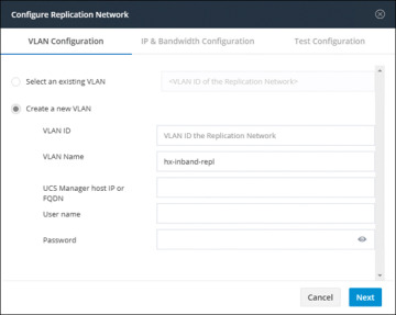
Figure 6-7 VLAN Creation for Replication Network
UCS Manager host IP or FQDN: The host IP address or FQDN for the UCS Manager
Username: The administrator username for Cisco UCS Manager
Password: The administrator password for Cisco UCS Manager
Step 4. Click Next.
Step 5. In the IP & Bandwidth Configuration tab, set the network parameters and the replication bandwidth (see Figure 6-8):
Subnet: The subnet for the replication network
Gateway: The gateway for the replication network
IP Range: The range of IP addresses for each converged node in the cluster plus one additional IP address (that is, N+1)
Add IP Range: Button for adding the specified IP range
Set replication bandwidth limit: The bandwidth that the replication network is allowed to consume
Set non-default MTU: MTU other than the default, which is 1500.
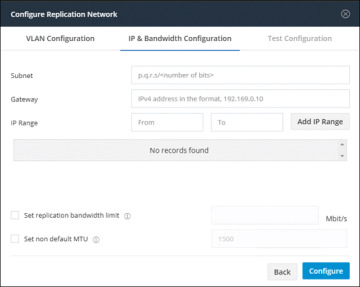
Figure 6-8 IP and Bandwidth Replication Settings
Step 6. Click Configure.
Step 7. In the Test Configuration tab, shown in Figure 6-9, check the replication network configuration.
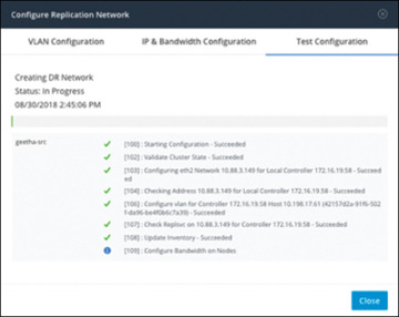
Figure 6-9 Replication Network Test Configuration
)
)
)
)
)
Replication Pair Overview
Once a replication network is configured and tested, pairing a replication cluster is the next step. Creating a replication cluster pair is a prerequisite for setting up VMs for replication. The replication network and at least one datastore must be configured before the replication pair can be created.
By pairing cluster 1 with cluster 2, you are specifying that all VMs on cluster 1 that are explicitly set up for replication can replicate to cluster 2 and that all VMs on cluster 2 that are explicitly set up for replication can replicate to cluster 1.
By pairing datastore A on cluster 1 with datastore B on cluster 2, you are specifying that for any VM on cluster 1 that is set up for replication, if it has files in datastore A, those files will be replicated to datastore B on cluster 2. Similarly, for any VM on cluster 2 that is set up for replication, if it has files in datastore B, those files will be replicated to data-store A on cluster 1.
Pairing is strictly one to one. A cluster can be paired with no more than one other cluster. A datastore on a paired cluster can be paired with no more than one datastore on the other cluster.
Procedure for Creating Replication Pair
To create a replication pair, create a datastore on the local network and create a datastore on the remote network. Then follow these steps:
Step 1. From HX Connect, log in to either the local cluster or the remote cluster as a user with administrator privileges.
Step 2. Select the Replication page and then select Pair Cluster, which will bring up the Create New Replication Pair window. Figure 6-10 shows where to pair the new cluster for replication in HX Connect.
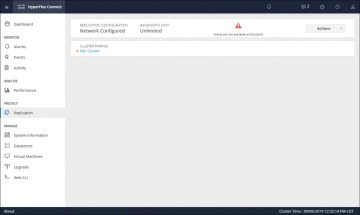
Figure 6-10 Replication Pair Cluster
Step 3. Enter a name for the replication pair on the Name tab, as shown in Figure 6-11, and click Next. The name, which cannot be changed, is set for both the local and remote clusters.
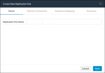
Figure 6-11 Replication Pair Name
Step 4. On the Remote Connection tab (see Figure 6-12), enter the following information:
Management IP or FQDN: The IP address or FQDN for the remote HX storage cluster
Username: The vCenter single sign-on or cluster-specific administrator username of the remote HX storage cluster
Password: The vCenter single sign-on or cluster-specific password of the remote HX storage cluster
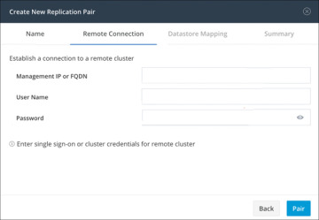
Figure 6-12 Replication Remote Connection
When you’re done with these entries, click Pair to pair with the replication remote cluster.
Step 5. Go to the Datastore Mapping tab, as shown in Figure 6-13, to view the data-store mapping between the local and remote clusters. The Local Datastore column shows the list of the configured datastores on the local HX storage cluster. The Remote Datastore column pairs the datastores between the HX storage clusters. Click Next.
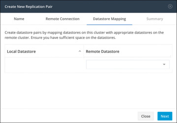
Figure 6-13 Datastore Mapping Between Clusters
Step 6. On the Summary tab, shown in Figure 6-14, review the summary of the data-store mapping. The Datastore field indicates the selected datastore on this local HX storage cluster. The Target Datastore field indicates the datastore on the remote HX storage cluster to which the replication snapshot is copied. Click Map Datastores.
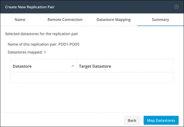
Figure 6-14 Datastore Mapping Summary
)
)
)
)
)
Protecting Virtual Machines
After a replication cluster is formed, the next step is to protect the virtual machines in the clusters. The following attributes are required to protect the virtual machines:
Replication interval, which is the frequency of replication
A start time (within the next 24 hours), which specifies the first time replication is attempted for that virtual machine
Whether the replication snapshot should be taken with the virtual machine quiesced or not
Protection attributes can be created and assigned to protection groups. To assign the protection attributes to virtual machines, you can add them to a protection group. For example, suppose there are three classes of protection: gold, silver, and bronze. You can set up a protection group for each class, with replication intervals such as 5 or 15 minutes for gold, 4 hours for silver, and 24 hours for bronze. Most of your VMs could be protected by merely adding them to one of the three already created protection groups.
To protect virtual machines, you can choose from the following methods:
Independently: Select one virtual machine and configure it. Set the replication schedule and the VMware quiesce option for the specific virtual machine. Changes to the replication settings will only affect the independently protected virtual machine. The virtual machine is not included in a protection group.
Existing protection group: Select one or more virtual machines and add them to an existing protection group. The schedule and VMware quiesce option settings are applied to all the virtual machines in the protection group. When the protection group settings are changed, the changes are applied to all the virtual machines in the protection group.
New protection group: Select two or more virtual machines and choose to create a new protection group. Define the protection group name, schedule, and VMware quiesce option settings. These settings are applied to all the virtual machines in the protection group. When the protection group settings are changed, the changes are applied to all the virtual machines in the protection group.
Creating Protection Groups
Protection groups provide protection to the VMs where they are created. If protection groups have protected virtual machines that replicate to the remote cluster, these protection groups are listed in HX Connect. Before staring the configuration, ensure that replication network and replication pair are configured. Then follow these steps:
Step 1. Log in to HX Connect as an administrator.
Step 2. On the Replication page, click Create Group (see Figure 6-15.
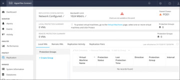
Figure 6-15 Creating a Protection Group
Step 3. Enter the following information in the Create Protection Group dialog (see Figure 6-16):
Protection Group Name: The name for the new protection group for this local cluster
Protect virtual machines in this group every: The frequency at which virtual machines are to be replicated to the paired cluster
Start protecting the virtual machines immediately: Radio button to start replication immediately after adding the first virtual machine to the protection group
Start protecting the virtual machines at: Radio button to set a specific time for the first replication to start
Use VMware Tools to quiesce the virtual machine: Check box to have HX Data Platform quiesce the virtual machines before taking the replication snapshot
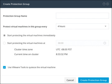
Figure 6-16 Protection Group Settings
Before starting replication, ensure that at least one virtual machine is added to the protection group and the scheduled start time is reached. To specify the protection start time, click in the time field and select an hour and minute.
Step 4. Click Create Protection Group to add the new group to the Protection Groups tab.
)
)
When the protection group is created, the next step is to add virtual machines to the created group.
Protecting Virtual Machines
This section describes how to protect multiple virtual machines using an existing protection group. Before starting, make sure that the replication network and replication pair are configured and that a protection group is created prior to adding the virtual machines. Then follow these steps:
Step 1. Log in to HX Connect as an administrator.
Step 2. On the Virtual Machines page, select one or more unprotected virtual machines from the list (see Figure 6-17).
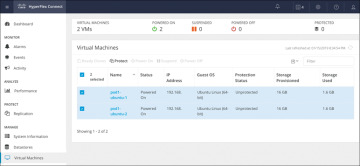
Figure 6-17 Virtual Machine Display Window
Step 3. Click Protect.
Step 4. In the Protect Virtual Machines dialog (see Figure 6-18), verify the selected virtual machine name(s), storage provisioned, and storage used by the VMs
Add to an existing protection group: Click this radio button to select an existing protection group from the pull-down list.
Create a new protection group: Select this radio button to create a new protection group for the local cluster.
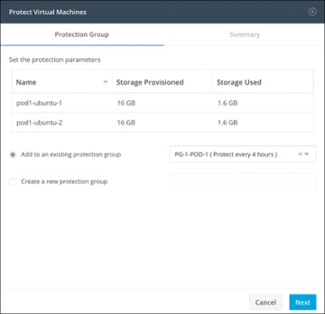
Figure 6-18 Protect Virtual Machines Window: Protection Group Tab
Step 5. Click Next.
Step 6. Confirm the information shown on the Summary tab (see Figure 6-19) and click Add to Protection Group.
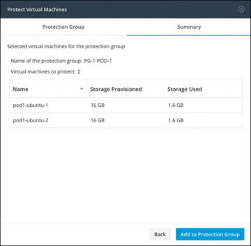
Figure 6-19 Protect Virtual Machines Window: Summary Tab
)
)
)
)
Disaster Recovery Overview
Disaster recovery is performed when the source site is unreachable and it is necessary to fail over the VMs and the protected groups to the target cluster. The process recovers the VM on the target cluster. The following bullet points describe the commonly used operations for disaster recovery:
Testing VM recovery: Testing VM recovery gives the user the ability to test recovery without breaking replication. It can bring up the user VM workload on the target to verify the contents of the VM.
Recovering virtual machines: Recovering virtual machines means restoring the most recent replication snapshot from the target (recovery) cluster. Once recovery starts, all the scheduled replication is stopped.
Planned migration: Performing a planned migration pauses the replication schedule, replicates the most recent copy, recovers on the target, switches the ownership from the source to the target, and resumes replication on the target that is now the new source.
Compatibility Matrix for Disaster Recovery Operations
The compatibility matrix in Table 6-2 lists the disaster recovery operations that are supported when an HX Data Platform version 3.5(x) cluster is paired with an HX Data Platform version 3.5(x) or 3.0(1x) cluster.
Table 6-2 Disaster Recovery Operation Compatibility Matrix
Feature |
3.5(x) Paired with 3.5(x) |
3.5(x) Paired with 3.0(1x) |
Replication |
✓ |
✓ |
Cluster pairing |
✓ |
✓ |
Datastore mapping |
✓ |
✓ |
Protection |
✓ |
✓ |
Planned migration (single-click using HX Connect) |
✓ |
✗ |
Planned migration (Multistep stcli or WebCLI and HX Connect for recovery) |
✓ |
✓ |
Test recovery using HX Connect |
✓ |
✓ |
Recover using HX Connect |
✓ |
✓ |
Re-protect using HX Connect |
✓ |
✗ |
Re-protect (multistep stcli or WebCLI) |
✓ |
✓ |
Testing Virtual Machine Recovery
Testing recovery does not disrupt the running clusters. The intent is to verify that, in the event of an actual disaster, the VMs will be recoverable. Using the HX Connect user interface to test VM recovery, you can run a maximum of 10 tasks in a sequence without waiting for the previously submitted task to complete. The following section describes the steps needed to properly test virtual machine recovery:
Step 1. Log in to HX Connect on the target cluster as administrator.
Step 2. Navigate to the Replication page and select the Remote VMs tab. Figure 6-20 shows the Replication page for remote VMs for test recovery.
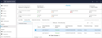
Figure 6-20 Replication Test Recovery
Step 3. To test the recovery process, select a protected VM and click the Test Recovery button. Figure 6-21 shows the test recovery parameters, which are as follows:
)
)
Figure 6-21 Test Recovery Parameters
Step 4. When you have finished setting the parameters in the Test Recovery Parameters dialog, click Recover VM.
Step 5. When the job completes, verify that the VM has been recovered to the HxRecoveryTest folder or the folder you designated.
Step 6. Power on the recovered VMs via vSphere Web Client or HTML5 vSphere Client to test their functionality.
Step 7. Repeat steps 3 through 6 for each VM you want to test.
Step 8. When the testing is completed, delete the test recovery VMs.
Recovering Virtual Machines
In the case of a site outage or the failure of a cluster, VMs can be recovered to their state as of the last successfully transmitted snapshot, running on the secondary or target cluster as part of a disaster recovery operation. This recovery operation assumes that the primary, or source, site and cluster is either offline or isolated in such a way that it can no longer communicate with the secondary, or target, site, and it cannot be managed. A recovery operation stops all replication between the two clusters; replication can be reestablished at a later time, after the faults or outages have been repaired. The following section describes the steps needed to properly recover virtual machines:
Step 1. Log in to HX Connect as administrator.
Step 2. Navigate to the Replication page and select the Remote VMs tab (see Figure 6-22).

Figure 6-22 Virtual Machine Recovery
Step 3. Select a protected VM and click the Recover button.
Step 4. To recover the VM and build a new VM on the local cluster, set the following options in the Recover VM on This Cluster dialog (see Figure 6-23):
)
)
Figure 6-23 Virtual Machine Recovery Parameters
Step 5. When you have finished setting the parameters in the Recover VM on This Cluster dialog, click Recover VM.
Step 6. Wait for the recovery to complete. View the recovered VM in the target vCenter.
Plan Migration
Performing planned migration pauses the replication schedule, replicates the most recent copy, recovers on the target, switches the ownership from the source to the target, and resumes replication on the target that is now the new source. The following section describes the steps needed to properly perform a planned migration:
Step 1. Log in to HX Connect as administrator.
Step 2. Navigate to the Replication page and select the Remote VMs tab.
Step 3. Select a protected VM and click Migrate.
Step 4. To migrate a VM, set the following options:
Resource Pool: Specify the location for the new VM to be stored.
Folders: Specify the location for the new VM to be stored.
Power On/Off: Select the status of the recovery VM.
Map Networks: Create a map between the source and the target cluster networks. These are the options:
Source Network: Indicates the network name at the source side on which the VM is connected.
Target Network: Select the target network where the VM has to be connected.
Step 5. Monitor the progress on the Activity page.
HyperFlex Backup
The Cisco HyperFlex HX Data Platform is a purpose-built, high-performance distributed file system that delivers a wide range of enterprise-class data management and optimization services. This platform redefines distributed storage technology, expanding the boundaries of hyperconverged infrastructure with independent scaling, continuous data optimization, simplified data management, and dynamic data distribution for increased data availability. This agile system is easy to deploy, manage, and scale as your business needs change, and it provides the first level of data availability. However, as with most other systems, a second layer of protection that is equally agile is recommended. HyperFlex can therefore integrate with third-party solutions such as Veeam Availability Suite, Cohesity, and Commvault.
Veeam Availability Suite
The Cisco HyperFlex system and Veeam Availability Suite solution is flexible, agile, and scalable infrastructure that is protected and easy to deploy. Building on top of the Cisco HyperFlex HX Data Platform’s built-in protection tools, Veeam Availability Suite expands data protection with local and remote backups and VM-level replication.
Veeam Availability Suite enables backup and replication of infrastructure VMs on Cisco HyperFlex clusters located in the same data center. Veeam Availability Suite, which includes the Veeam Repository, Veeam Proxy, and Veeam Backup Server, resides on a single Cisco UCS S3260 storage server, which provides up to 600 TB of raw storage capacity. Replication of the application VM is executed to a separate Cisco HyperFlex cluster.
Figure 6-24 provides a high-level view of Cisco HyperFlex with a Cisco S3260 storage server and Veeam Availability Suite and illustrates the following:
Replication of application VMs across Cisco HyperFlex clusters through Veeam Availability Suite
Backup of application VMs on a Cisco S3260 storage server
Management endpoints for Cisco HyperFlex, a Cisco UCS S3260 storage server, and Veeam Availability Suite
)
Figure 6-24 HyperFlex with Cisco S3260 Storage Server and Veeam Availability Suite Backup Solution
The Veeam Backup & Replication application operates at the virtualization layer and uses an image-based approach for VM backup. To retrieve VM data, no agent software needs to be installed inside the guest OS. Instead, Veeam Backup & Replication leverages vSphere snapshot capabilities and application-aware processing. When a new backup session starts, a snapshot is taken to create a cohesive point-in-time copy of a VM, including its configuration, OS, applications, associated data, system state, and so on. Veeam Backup & Replication uses this point-in-time copy to retrieve VM data. Image-based backups can be used for different types of recovery, including full VM recovery, VM file recovery, instant VM recovery, file-level recovery, and application item recovery.
The image-based approach allows Veeam Backup & Replication to overcome shortfalls and limitations of traditional backups. It also helps streamline recovery verification and the restoration process; to recover a single VM, there is no need to perform multiple restore operations. Veeam Backup & Replication uses a cohesive VM image from the backup to restore a VM to the required state without the necessity for manual reconfiguration and adjustment. In Veeam Backup & Replication, backup is a job-driven process in which one backup job can be used to process one or more VMs. A job is a configuration unit of the backup activity. Essentially, the job defines when, what, how, and where to back up. It indicates what VMs should be processed, what components should be used for retrieving and processing VM data, what backup options should be enabled, and where to save the resulting backup file. Jobs can be started manually by the user or scheduled to run automatically. The resulting backup file stores compressed and deduplicated VM data. Compression and deduplication are done by the Veeam proxy server.
Regardless of the backup method you use, the first run of a job creates a full backup of a VM image. Subsequent job runs are incremental; that is, Veeam Backup & Replication copies only those data blocks that have changed since the last backup job run. To keep track of changed data blocks, Veeam Backup & Replication uses different approaches, including VMware’s Changed Block Tracking (CBT) technology.
Changed Block Tracking
To perform an incremental backup, Veeam Backup & Replication needs to know which data blocks have changed since the previous job run. Figure 6-25 shows Veeam full and incremental backups.
)
Figure 6-25 Veeam Full and Incremental Backups
For VMware VMs with hardware version 7 or later, Veeam Backup & Replication employs VMware vSphere Changed Block Tracking (CBT), which is a native VMware feature. Instead of scanning Virtual Machine File System (VMFS), Veeam Backup & Replication queries CBT on vSphere through the VMware vStorage APIs for Data Protection (VADP) and gets the list of blocks that have changed since the last run of this particular job. Use of CBT increases the speed and efficiency of block-level incremental backups. CBT is enabled by default; if necessary, you can disable it in the settings of a specific backup job.
Veeam Backup & Replication offers a number of recovery options for various disaster recovery scenarios:
Veeam Explorer: Enables you to restore single application-specific items.
Instant VM Recovery: Enables you to instantly start a VM directly from a backup file.
Full VM recovery: Enables you to recover a VM from a backup file to its original location or to another location.
VM file recovery: Enables you to recover separate VM files (virtual disks, configuration files, and so on).
Virtual drive restore: Enables you to recover a specific hard drive of a VM from the backup file, and attach it to the original VM or to a new VM.
Windows file-level recovery: Enables you to recover individual Windows guest OS files (from FAT, NTFS, and ReFS).
Multi-OS file-level recovery: Enables you to recover files from 15 different guest OS file systems.
Veeam Backup & Replication uses the same image-level backup for all data recovery operations. You can restore VMs, VM files and drives, application objects, and individual guest OS files to the most recent state or to any available restore point.
Cohesity
Cohesity running alongside Cisco HyperFlex within a Cisco UCS domain offers a consolidated system that provides the primary storage, workload hosting, data protection, and file services required for most virtualized data centers, all within a single unified architecture. Cohesity and Cisco HyperFlex share complementary data center technologies, both utilizing a distributed file system architecture that is designed for high availability. Through a shared-nothing topology, there is no single point of failure, and there are no inherent bottlenecks, and both performance and capacity can scale linearly as more physical nodes are added to the clusters. The distributed file system spans all nodes in the cluster and natively provides global deduplication, compression, and encryption.
With Cisco HyperFlex integration, Cohesity DataProtect software takes virtual machine snapshots directly on HyperFlex, which creates a storage-native snapshot for the virtual machine. Because this snapshot is native to HyperFlex, it has very similar performance characteristics as that of the original base disk when compared to the performance when using standard VMware redo-log-based snapshots. After a snapshot is taken, Cohesity DataProtect proceeds to back up the virtual machine data, and then the snapshot is deleted through the HyperFlex API. Using native snapshots eliminates common delays and I/O penalties and improves application performance by using the underlying HyperFlex distributed storage technology to create and consolidate the snapshots.
Cohesity Protection
During a Cohesity Protection job, a new snapshot of the virtual machine is taken, and that snapshot is transferred via the network to the storage domain configured in the job. This constitutes a new incremental backup of that virtual machine. Once the snapshot is transferred, the snapshot of the virtual machine is deleted in the source hypervisor node. If the virtual machine being backed up was already running with an active snapshot, the new snapshot taken by Cohesity is a child of the existing snap, and then it is deleted, coalescing the changes back into the existing snapshot level where the virtual machine was already running. If storage snapshot provider integration with Cisco HyperFlex is enabled, then all of these snapshots are taken as HX native snapshots. If the HX native snapshot attempt fails, such as when an existing VMware standard redo-log snapshot exists, the protection job falls back to taking a standard VMware snapshot.
Cohesity Recovery
A recovery job can be initiated to restore a virtual machine from the backed-up snapshots and return the virtual machine to service. A unique aspect of the Cohesity software is the sequence of the recovery process. When a recovery job is started, the Cohesity system presents an NFS-based datastore from itself, which is mounted to the ESXi host, inside of which are the virtual machine files that have been bloomed from the snapshots. The virtual machine is then registered in vCenter from this location, and the virtual machine is powered on. This process returns the recovered virtual machine to service much faster than would a typical recovery process because the virtual machine immediately runs with its virtual files sourced from the Cohesity NFS datastore. After the virtual machine is powered on, a storage vMotion relocates the virtual machine files to their original location. The benefit of this recovery workflow is amplified when multiple simultaneous virtual machine recoveries are needed because the time to return the virtual machines to service is very low, and the remaining process of relocating the virtual machines via storage vMotion happens in the background while the virtual machines are already online. A recovered virtual machine has no snapshots, even if the virtual machine originally had snapshots at the time of the backup that is being restored.
Commvault
Commvault software natively protects VMware and Hyper-V workloads on Cisco HyperFlex for fast protection and to meet demanding RTO and RPO requirements. For VMware, Commvault IntelliSnap technology leverages Cisco HyperFlex snapshots, and for Hyper-V, Commvault application-aware technology ensures application-consistent backups. It embraces and utilizes all cloud options, instantly migrating data between any virtualized platform, any public or private cloud platform, and any on-premises infrastructure. It also seamlessly adopts scale-up and scale-out architecture options to maximize cost-effectiveness and ensure that users have the scale capabilities needed based on workload size and criticality.
Figure 6-26 shows the architecture of Commvault software for Cisco HyperFlex.
)
Figure 6-26 Commvault Software for Cisco HyperFlex Architecture
Summary
This chapter provides an overview of the HX Data Platform disaster recovery feature. It also discusses the configuration steps required to properly enable the feature. Finally, the chapter introduces the supported third-party solutions to use as a second layer of protection for HyperFlex Data Platform.