In this sample chapter from Deploying ACI: The complete guide to planning, configuring, and managing Application Centric Infrastructure, learn how to enable Layer 3 communication and integrate with routing protocols you may already be using in your environment.
Connecting ACI to your existing network is a very important step. The connectivity choices that are made can affect the scalability, redundancy, and complexity of your design. In previous chapters, we discussed connectivity for Layer 2 communication. In this chapter, we discuss how to enable Layer 3 communication and integrate with routing protocols you may already be using in your environment. Specifically, we cover the following topics:
Physical connectivity options
Routing protocols
External EPGs and contracts
Multitenant routing considerations
Transit routing
WAN integration
Quality of Service
Multicast
Layer 3 Physical Connectivity Considerations
Getting the most out of ACI means moving Layer 3 routing into the fabric. To move routing into the fabric, we have to have a way to advertise these hosted networks to the rest of the world as well as allow communication to and from the fabric and networks via Layer 3. A data center fabric is home to many critical applications, and these L3 outside links are their lifelines to the outside world. When you’re considering your Layer 3 design, it is important to review some of the following items:
North/south bandwidth requirements
Expected level of redundancy
Media types
Neighbor devices such as routers, switches, and firewalls
Routing protocol or static routes
These decision points will lead you to select the correct physical device for your border leaf, such as a Nexus 9K that supports copper or fiber host-facing ports at 10G, 40G, or 100G, or, as we will discuss later in this chapter, the capability to integrate with other technologies such as the Nexus 7K or ASR platform. Once the physical platform is decided upon, the next decision points will be how many links, which technologies to use, and whether you will use a routing protocol or static routes. Figure 6-1 shows some of these options.
)
Figure 6-1 L3 Out Routed Interface Options for Border Leafs
We will discuss the major decision points in the following sections.
Routed Ports Versus Switched Virtual Interfaces
ACI has the capability to use routed ports, subinterfaces, and switched virtual interfaces (SVIs) for its Layer 3 external connections. The port configuration you choose (Access, Port Channel, VPC) will restrict the features you have the ability to deploy. An example is that ACI supports routed access ports, but not routed port channels. In general, it is a best practice to deploy routed ports when possible instead of SVIs for external routed connections for the following reasons:
SVIs require you to run the port as an L2 port.
L2 ports require spanning tree on the neighboring switch. Spanning tree ports traditionally have to transition through listening and learning states.
BPDUs will be sent from the neighboring switch towards ACI.
If the VLAN is reused on other ports on the neighboring switch, or even additional ACI leafs or ports, it can expose the network to risk (see the “Outside Bridge Domains” section, next).
Given these factors, routed ports have less risk and converge faster than ports using SVIs. In traditional networking, recommended practice dictates that you use routed port channels if possible. ACI does not currently support this configuration. ACI does support the configuration of multiple routed access ports for a single L3 Out, creating equal-cost multipath and redundancy through multiple links, as shown in Figure 6-2. You will generally find that routing protocols and static routes support at least four equal-cost multipath links.
)
Figure 6-2 Using Multiple Routed Access Ports for Redundancy
Your architecture may dictate the use of subinterfaces and/or switched virtual interfaces. This type of configuration is usually found in the scenarios listed below:
Connection to legacy devices.
Migration from your existing network.
Integration of L4-7 devices.
Single interface to host multiple L3 Outs for multiple tenants. Routing relationships could be established for different private networks (VRFs) or tenants on the same physical interface
Figure 6-3 shows supported configurations for L3 Out using SVI.
)
Figure 6-3 Supported Configurations for L3 Out when Using SVIs
With an SVI interface, the same physical interface that supports Layer 2 and Layer 3 can be used for a Layer 2 outside connection as well as a Layer 3 outside connection.
It is best practice to use a port channel or (whenever possible) a virtual port channel for increased redundancy. If a shared gateway or gateway redundancy is also a requirement, it is possible to use a secondary IP address or Hot Standby Routing Protocol (HSRP), which is supported in ACI software release 2.2.
Outside Bridge Domains
L3 Out can be configured with Layer 3 interfaces, subinterfaces, or SVIs. When configuring an SVI on L3 Out, you can specify a VLAN encapsulation. Specifying the same VLAN encapsulation on multiple border leaf nodes in the same L3 Out results in the configuration of an external bridge domain. Compared to a bridge domain inside the fabric, there is no mapping database for the L3 Out, and the forwarding of traffic at Layer 2 is based on “flood and learn” over VXLAN. It is recommended that you limit the use of the same SVI encapsulation to two leafs configured in vPC mode. At press time, it is not supported to have an L3 Out made of non-EX (first-generation) leafs consisting of two or more vPC pairs (four or more leafs, two vPC domains) with SVIs, all with the same VLAN encapsulation. If the destination MAC is the SVI MAC address, the traffic is routed in the fabric as already described.
Bidirectional Forwarding Detection
Cisco ACI Software Release 1.2(2g) added support for bidirectional forwarding detection (BFD), which is a software feature used to provide fast failure detection and notification to decrease the convergence times experienced in a failure scenario. BFD is particularly useful in environments where Layer 3 routing protocols are running over shared Layer 2 connections, or where the physical media does not provide reliable failure detection mechanisms. Some of the benefits of using BFD are as follows:
It provides subsecond Layer 3 failure detection.
It supports multiple client protocols (for example, OSFP, BGP, EIGRP).
It is less CPU-intensive than routing protocol hello messages (the BFD echo function uses the data plane).
The client protocol is notified when BFD detects a failure. The client protocol does not need to run low hello timers.
In Cisco ACI, BFD is supported on L3 Out interfaces only, where BGP, OSPF, EIGRP, or static routes are in use. BFD is not supported for fabric interfaces (that is, interfaces used to connect leaf and spine nodes together). BFD in Cisco ACI has the following characteristics:
BFD Version 1 is used.
Cisco ACI BFD uses asynchronous mode (that is, both endpoints send hello packets to each other).
BFD is not supported for multihop BGP. By default, a BGP global policy exists for both IPv4 and IPv6 sessions. The default timers specified in this policy have a 50-millisecond interval with a multiplier of 3, as shown in Figure 6-4.
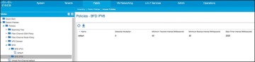
Figure 6-4 BFD Configuration
)
This global default policy can be overridden if required by creating a new nondefault policy and assigning it to a switch policy group and then a switch profile. BFD is also configurable on a per-tenant basis (under Networking > Protocol Policies) and will override the global BFD policy.
It is recommended that you enable BFD on L3 Out SVIs wherever possible to help ensure fast failure detection (assuming that the connected device supports it). For routed interfaces and subinterfaces, BFD may still be enabled, although physical interface mechanisms should ensure fast failure detection in most circumstances. In summary, here are some common uses for BFD or instances where BFD is needed:
L3 hop over an intermediate L2 connection
Protocol software failures
Unidirectional link
When physical media does not provide reliable failure detection
When the routing protocol is running over an interface type that does not provide link failure notification, such as SVI
BFD may not be needed with directly connected point-to-point L3 links. A link-down event is typically detected faster than BFD.
Access Port
An access port is a single port used for connectivity in an ACI network. You have the capability to use an access port for Layer 3 external network connectivity as well. It is a best practice to use multiple access ports running as routed ports for an external Layer 3 network connection. Figure 6-5 shows an example of this configuration.
Port Channel
A port channel bundles individual interfaces into a group to provide increased bandwidth and redundancy. Port channeling also load-balances traffic across these physical interfaces. For this reason, the recommended practice is to deploy port channels in even numbers. The port channel stays operational as long as at least one physical interface within the port channel is operational. In ACI, you will be creating the port channel using multiple leaf ports on a fixed configuration switch. It is a best practice to diversify port channels across different physical line cards and/or ASIC port groups on the neighboring switch for physical diversity, if possible, as shown in Figure 6-6.
)
Figure 6-5 Using Multiple Routed Access Ports for Redundancy
)
Figure 6-6 Port Channel Diversity
You create a port channel by bundling compatible interfaces. You can configure and run either static port channels or port channels running the Link Aggregation Control Protocol (LACP). These settings are implemented in ACI based on the configuration of your fabric access policy. It is important that the settings on both sides of your port channel match, as shown in Figure 6-7.
)
Figure 6-7 Configuration Parity
Once the port channel is up and running at Layer 2, ACI will create an outside bridge domain and bring up the SVIs or subinterfaces as configured in your external routed network configuration.
Virtual Port Channel
Virtual Port Channel (vPC) is a virtualization technology that presents paired devices as a unique Layer 2 logical node to access layer devices or endpoints. In the past, you may have heard this technology referred to as Multichassis EtherChannel. A virtual port channel allows links that are physically connected to two different devices to appear as a single port channel to a third device. The third device can be a switch, server, or any other networking device that supports link aggregation technology. vPC provides the following technical benefits:
Eliminates Spanning Tree Protocol (STP) blocked ports
Uses all available uplink bandwidth
Allows dual-homed servers to operate in active/active mode
Provides fast convergence upon link or device failure
Offers dual active/active default gateways for servers
vPC also leverages native split-horizon/loop management provided by port-channeling technology: a packet entering a port channel cannot immediately exit that same port channel.
By using vPC, users get the following immediate operational and architectural advantages:
Simplified network design
Building a highly resilient and robust Layer 2 network
Scaling available Layer 2 bandwidth, increasing bisectional bandwidth
vPC leverages both hardware and software redundancy aspects:
vPC uses all port channel member links available so that in case an individual link fails, a hashing algorithm will redirect all flows to the remaining links.
A vPC domain is composed of two peer devices. Each peer device processes half of the traffic coming from the access layer. In case a peer device fails, the other peer device will absorb all the traffic with minimal convergence time impact.
Each peer device in the vPC domain runs its own control plane, and both devices work independently. Any potential control plane issues stay local to the peer device and do not propagate or impact the other peer devices.
You can configure dynamic routing protocol peering over a vPC for an L3 Out connection by specifying the same SVI encapsulation on both vPC peers, as illustrated in Figure 6-8. The SVI configuration instantiates an outside bridge domain. The external router peers with the SVI on each leaf device. In addition, the SVIs on the two leaf devices peer with each other. Failure of a vPC port channel to one leaf will not bring down the neighbor adjacency.
If static routing is required toward the fabric, you must specify the same secondary IP address on both vPC peer devices’ SVIs. This configuration is not supported when using a dynamic routing protocol.
)
Figure 6-8 Dynamic Routing: Peering over vPC
Gateway Resiliency with L3 Out
Some design scenarios may require gateway resiliency: for example, where external services devices (such as firewalls) require static routing to subnets inside the Cisco ACI fabric, as shown in Figure 6-9.
)
Figure 6-9 L3 Out Secondary Address Configuration
In the example in Figure 6-9, a pair of Cisco ASA firewalls (running in active-standby mode) are attached to the Cisco ACI fabric. On the fabric side, L3 Out is configured to connect to the firewalls. On the firewalls, a static route exists pointing to internal Cisco ACI subnets through the 192.168.1.254 address. This .254 address is configured on the fabric as a shared secondary address under the L3 Out configuration. When configuring the interface profile under L3 Out, you have configuration options for Side A, Side B, and secondary addresses, as shown in Figure 6-10.
In this example, 192.168.1.254 is configured as the shared secondary address, which is then used as the next hop for the static route configured on the firewall.
Hot Standby Routing Protocol
Hot Standby Routing Protocol (HSRP) provides network redundancy for IP networks, ensuring that user traffic immediately and transparently recovers from first-hop failures in network edge devices.
)
Figure 6-10 SVI Configuration
By sharing an IP address and a MAC (Layer 2) address, two or more routers can act as a single virtual router. The members of the virtual router group continually exchange status (hello) messages. This way, one router can assume the routing responsibility of another, should it go out of commission for either planned or unplanned reasons. Hosts continue to forward IP packets to a consistent IP and MAC address, and the changeover of devices doing the routing is transparent.
Using HSRP, a set of routers works in concert to present the illusion of a single virtual router to the hosts on the LAN. This set is known as an HSRP group or a standby group. A single router elected from the group is responsible for forwarding the packets that hosts send to the virtual router. This router is known as the active router. Another router is elected as the standby router. In the event that the active router fails, the standby assumes the packet-forwarding duties of the active router. Although an arbitrary number of routers may run HSRP, only the active router forwards the packets sent to the virtual router.
ACI supports HSRP on L3 Out routed interfaces and routed subinterfaces, specifically where customers may connect an external L2 network to ACI, but do not want to extend the L2 network in question into ACI using traditional means. In this configuration, the HSRP hello messages are exchanged via the external L2 network, and do not go over the fabric links within the fabric. Currently, HSRP is not supported on SVIs. Figure 6-11 demonstrates an example of this.
)
Figure 6-11 HSRP Example in ACI
Here are the current HSRP features supported in ACI:
Version 1 and 2
Support for IPv4 and IPv6
Supports BFD
Authentication (MD5 and simple authentication)
Configurable timers (min 250 msec hello timer)
Configurable vMAC or option to use burnt-in-MAC address
Priority/preemption
With that in mind, the current guidelines and limitations are as follows:
The HSRP state must be the same for both HSRP IPv4 and IPv6. The priority and preemption must be configured to result in the same state after failovers.
Currently, only one IPv4 and one IPv6 group are supported on the same subinterface in Cisco ACI.
Users must configure the same MAC address for IPv4 and IPv6 HSRP groups for dual-stack configurations.
HSRP VIP must be in the same subnet as the interface IP.
It is recommended that you configure interface delay for HSRP configurations.
Object tracking on HSRP is not supported.
HSRP is not supported on SVI; therefore, no VPC support for HSRP is available.
Multiple group optimization (MGO) is not supported with HSRP.
ICMP IPv4 and IPv6 redirects are not supported.
High availability and Non-Stop Forwarding (NSF) are not supported because HSRP is not restartable in the Cisco ACI environment.
There is no extended hold-down timer support because HSRP is supported only on leaf switches. HSRP is not supported on spine switches.
HSRP version change is not supported in APIC. You must remove the configuration and reconfigure.
HSRP Version 2 does not interoperate with HSRP Version 1. An interface cannot operate both Version 1 and Version 2 because both versions are mutually exclusive. However, the different versions can be run on different physical interfaces of the same router.
Routing Protocols
As of Release 2.0, Cisco ACI supports the following routing mechanisms:
Static routing (supported for IPv4 and IPv6)
OSPFv2 for regular, stub, and not-so-stubby-area (NSSA) areas (IPv4)
OSPFv3 for regular, stub, and NSSA areas (IPv6)
EIGRP (IPv4 only)
iBGP (IPv4 and IPv6)
eBGP (IPv4 and IPv6)
Through the use of subinterfaces or SVIs, border leaf switches can provide L3 Out connectivity for multiple tenants with one physical interface.
Static Routing
Routers forward packets using either route information from route table entries that you manually configure or the route information that is calculated using dynamic routing algorithms.
Static routes, which define explicit paths between two routers, cannot be automatically updated; you must manually reconfigure static routes when network changes occur. Static routes use less bandwidth than dynamic routes. No CPU cycles are used to calculate and analyze routing updates.
Static routes should be used in environments where network traffic is predictable and where the network design is simple. Static routes should not be used in large, constantly changing networks because static routes cannot react to network changes.
Static routes are very easy to configure in ACI. When you configure your L3 Out, a routing protocol will not be selected. Later in the process when a node is defined, you will also define the static routes. When you define the static route, you will be able to modify the following parameters:
Prefix
Priority for the static route
Next hop and next hop priority (the absence of a next hop adds a null route)
Enable BFD
As you would expect, the configuration is very straightforward. This configuration does not exchange routes with neighboring devices. Static routes will need to be added on the neighboring devices as well, so that traffic has a return path.
Enhanced Interior Gateway Routing Protocol
Enhanced Interior Gateway Routing Protocol (EIGRP) was Cisco’s proprietary routing protocol, based on IGRP, but it’s now an open standard. EIGRP is a distance vector routing protocol, with optimizations to minimize routing instability incurred after topology changes and the use of bandwidth and processing power in the router. Most of the routing optimizations are based on the Diffusing Update Algorithm (DUAL), which guarantees loop-free operation and provides fast router convergence.
The EIGRP routing protocol is very easy to configure and manage. For this reason, EIGRP is widely deployed across Cisco customers and is supported in ACI. To become an EIGRP neighbor, three essential configuration values must be matched: active hello packets, autonomous system number (ASN), and K values. EIGRP may use five K values or metric components to select the best route for the routing table. These are Bandwidth, Load, Delay, Reliability, and MTU. By default, EIGRP uses only two components: Bandwidth and Delay. When you configure a routing protocol on the L3 Out connection, you will select EIGRP. It is at this point that the AS number is able to be configured, as shown in Figure 6-12.
)
Figure 6-12 Configuring EIGRP on a Routed Outside Connection or L3 Out
During the configuration, you will add a node and interface profile. When the node and router ID are configured, avoid using the loopback. Loopbacks should be used only in BGP routing protocol configuration.
When the EIGRP interface profile is added, and the protocol profile is configured, ACI will ask for an EIGRP interface policy. It is here where the final K values (Bandwidth and Delay) will be configured. The EIGRP interface policy will then be applied to the interface that you choose in the next screens.
Open Shortest Path First
Open Shortest Path First (OSPF) is a routing protocol developed for IP networks by the Interior Gateway Protocol working group of the Internet Engineering Task Force (IETF). It was derived from several research efforts, including a version of OSI’s IS-IS routing protocol.
OSPF has two primary characteristics:
It is an open protocol. Its specification is in the public domain (RFC 1247).
It is based on the Shortest Path First (SPF) algorithm, sometimes known as the Dijkstra algorithm.
OSPF is a link-state routing protocol that calls for the sending of link-state advertisements (LSAs) to all other routers within the same hierarchical area. Information on attached interfaces, metrics used, and other variables are included in OSPF LSAs. As OSPF routers accumulate link-state information, they use the SPF algorithm to calculate the shortest path to each node.
OSPF is widely deployed in enterprises and is a go-to standard for open routing protocols. ACI supports external connectivity to external OSPF routers on OSPF normal areas, NSSA areas, and stub areas, including Area 0 (backbone area). Keep the following points in mind as you are configuring and using OSPF with ACI:
ACI border leafs running OSPF are always autonomous system boundary routers (ASBRs).
All external routes learned in OSPF are redistributed into MP-BGP.
MP-BGP routes are redistributed into OSPF as external Type-2 routes.
OSPF areas on different border leafs (border leaf pairs) are different OSPF areas, even if area IDs match, as shown in Figure 6-13.
Supports IPv4 (OSPFv2) and IPv6 (OSPFv3).
ACI border leaf switches follow OSPF protocol rules, as shown in Figure 6-14.
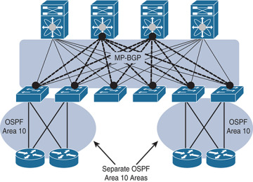
Figure 6-13 OSPF Areas on Different Border Leaf Switches Are Different OSPF Areas
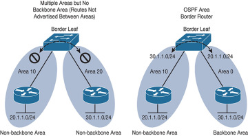
Figure 6-14 ACI Border Routers Follow Traditional OSPF Rules
)
)
When you configure a routing protocol on the L3 Out connection, you will select OSPF. It is at this point that the particulars of your OSPF area and the area number are configured, as shown in Figure 6-15.
)
Figure 6-15 Configuring the OSPF Area and Area ID for a Routed Outside or L3 Out
During the configuration, you will add a node and interface profile. When the node and router ID are configured, avoid using the loopback. Loopbacks should only be used in a BGP routing protocol configuration. When the OSPF interface profile is added, and the protocol profile is configured, ACI will ask for authentication information as well as an OSPF policy. The OSPF policy (see Figure 6-16) is where you can manage parameters such as the type of link (broadcast or point-to-point), passive participation, BFD, and MTU ignore. The OSPF interface policy will then be applied to the interface(s) you choose in the next screens.
)
Figure 6-16 OSPF Interface Policy
OSPF Summarization
For OSPF route summarization, two options are available: external route summarization (equivalent to the summary-address configuration in Cisco IOS Software and Cisco NX-OS Software) and inter-area summarization (equivalent to the area range configuration in Cisco IOS Software and NX-OS).
When tenant routes or transit routes are injected into OSPF, the Cisco ACI leaf node where the L3 Out connection resides is acting as an OSPF autonomous system boundary router (ASBR). In this case, the summary-address configuration (that is, external route summarization) should be used. Figure 6-17 illustrates this concept.
)
Figure 6-17 OSPF Summary-Address Operation
For scenarios where there are two L3 Out connections, each using a different area and attached to the same border leaf switch, the area range configuration will be used to summarize, as shown in Figure 6-18.
The OSPF route summarization policy is used to determine whether the summarization will use the area range or summary-address configuration, as shown in Figure 6-19.
In this example, checking the Inter-Area Enabled box means that area range will be used for the summary configuration. If this box is unchecked, summary address will be used.
)
Figure 6-18 OSPF Area Range Operation
)
Figure 6-19 OSPF Route Summarization
Border Gateway Protocol
The Border Gateway Protocol (BGP) is an inter-autonomous system routing protocol. An autonomous system (AS) is a network or group of networks under common administration using common routing policies. BGP is used to exchange routing information for the Internet and is the protocol used between ISPs. Customer networks, such as universities and corporations, usually employ an interior gateway protocol (IGP) such as Routing Information Protocol (RIP), Enhanced Interior Gateway Routing Protocol (EIGRP), or Open Shortest Path First (OSPF) for the exchange of routing information within their networks. Customers connect to ISPs, and ISPs use BGP to exchange customer and ISP routes. When BGP is used between autonomous systems, the protocol is referred to as external BGP (eBGP). If a service provider is using BGP to exchange routes within an autonomous system, the protocol is referred to as interior BGP (iBGP).
Application Centric Infrastructure (ACI) has the capability to peer with external BGP networks and redistribute the routing information throughout the fabric. To use this functionality, you will have to select BGP as the routing protocol when you create the L3 routed outside connection. By default, ACI will use the ASN that was defined when the route reflectors were configured during fabric setup.
iBGP design best practices need to be followed for the iBGP deployment between the ACI border leaf switches and external routers. The ACI border leaf needs to have iBGP sessions with all BGP speakers within the AS. In cases where the route reflector technology is deployed, ACI border leaf switches need to have iBGP sessions with all route reflectors in the BGP Route Reflector cluster.
Notice that border leafs don’t have iBGP sessions among themselves. This is not required because border leaf switches can learn routes from each other through MP-BGP.
Unless you are using WAN integration, be sure to follow the VRF-lite best practices for the multitenant deployment scenarios. When the Layer 3 outside connection is required for each tenant, configure separate iBGP sessions for each tenant.
When you are configuring the routed outside connection, the BGP-specific configuration requires you to create a node profile with the following information:
Router IDs (for iBGP peering with external device) with static routes to the next-hop address. Note that a loopback should be created.
BGP peering details, such as the Neighbor IP.
The interface and interface profile you will use with port, IP, and VLAN encapsulation details.
A BGP peer connectivity profile, including the following:
Peer address
Authentication
Next you will create an external endpoint group. This group will represent all the devices (or a subset of devices) that are reachable through this L3 Out and BGP connection. Many enterprises use the subnet 0.0.0.0/0 to assign all external endpoints reachable via this link to the EPG that is being crafted.
Finally, in order to advertise prefixes from the fabric (leaf) to its neighbor, you need to associate the Layer 3 outside network with the bridge domain (which will create a route map) that contains the subnets you want to advertise. The subnets must be marked as advertised externally, and an application profile with an EPG linked to this bridge domain must be created. The public routes will then be advertised to all peers of the associated Layer 3 outside network.
BGP Route Profile
A route profile provides a control mechanism for routes with BGP peers. This can be viewed as a standard route map in the classic BGP configuration.
A route profile can be associated with any of the following:
Prefix
Bridge domain
Layer 3 outside network
When a route profile is associated with a bridge domain, all of the subnets under the bridge domain will be advertised with the same BGP community value. The software also allows the user to associate a route profile with a subnet of a bridge domain; this capability provides the flexibility to mark different BGP community values for different subnets. When a route profile is specified under both the bridge domain and the subnets of a bridge domain, the route profile under the subnet takes precedence.
A route profile with the name “default-export” can be configured and will be applied automatically to the Layer 3 outside network.
Outbound BGP Policy
The ACI border leaf switches support outbound BGP policy to set community or extended community values for tenant routes. The BGP community attributes (standard and extended) are commonly used by network architects to group together certain BGP routes and apply route policy by matching community values.
The following two types of communities are supported:
Standard community: regular:as2-nn2:<community_value>
regular:as2-nn2 is a keyword for the standard community.
Add a standard community value (for example 666:1001).
Extended community: extended:as4-nn2:<community_value>
extended:as4-nn2 is a keyword for the extended community.
Add a extended community value.
BGP Protocol Statistics
BGP protocol statistics can be viewed under Fabric > Inventory (see Figure 6-20). Investigate them by following these steps:
In the navigation pane, expand Pod ID > Leaf Switch ID > Protocols > BGP and click the corresponding tenant and private network.
Click various options, such as Neighbors, Interfaces, Routes, and Traffic to check different statistics related to BGP.
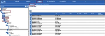
Figure 6-20 Validating Statistics
)
External Endpoint Groups and Contracts
It should be no surprise by now that communication with devices and networks outside the fabric is enabled through the use of groups and contracts. In the following subsection, we explore the flexibility of using these groups to provide external connectivity to devices inside the fabric.
External Endpoint Groups
An external endpoint group (EPG) carries the external network/prefix information. The ACI fabric maps external Layer 3 endpoints to the external EPG by using the IP prefix and mask. One or more external EPGs can be supported for each Layer 3 outside connection, depending on whether the user wants to apply a different policy for different groups of external endpoints. Figure 6-21 shows an example of this.
)
Figure 6-21 Multiple EPGs Associated with a Single L3 Out Connection
Most enterprises treat all outside endpoints equally for a given L3 outside link and create only one external EPG per L3 Out. This EPG will then be used when defining contracts between internal endpoint groups and the external L3 connection. This configuration still allows for a significant amount of control due to the contracts that are required between the traditional EPGs and the L3 Out EPGs. These contracts can be individually tailored per group or in a one-size-fits-all fashion.
Contracts Between L3 Out EPGs and Internal EPGs
An L3 Out connection is configured, and ACI interfaces are up. Neighbor relationships to external routers are formed and routes are being advertised. However, the cardinal rule of ACI is “zero trust,” and without a contract between the external EPG and the groups you would like to use it, no data shall pass. To enable end-to-end data connectivity, you need to create a contract between the internal EPG(s) and the external EPG. After you apply a contract between the L3 Out EPG and at least one internal EPG, data will be able to pass between the groups in the manner you specified in the contract.
Multitenant Routing Consideration
A common requirement of multitenant cloud infrastructures is the capability to provide shared services to hosted tenants. Such services include Active Directory, DNS, and storage. Figure 6-22 illustrates this requirement.
In Figure 6-22, Tenants 1, 2, and 3 have locally connected servers, respectively part of EPGs A, B, and C. Each tenant has an L3 Out connection linking remote branch offices to this data center partition. Remote clients for Tenant 1 need to establish communication with servers connected to EPG A. Servers hosted in EPG A need access to shared services hosted in EPG D in a different tenant. EPG D provides shared services to the servers hosted in EPGs A and B and to the remote users of Tenant 3.
In this design, each tenant has a dedicated L3 Out connection to the remote offices. The subnets of EPG A are announced to the remote offices for Tenant 1, the subnets in EPG B are announced to the remote offices of Tenant 2, and so on. In addition, some of the shared services may be used from the remote offices, as in the case of Tenant 3. In this case, the subnets of EPG D are announced to the remote offices of Tenant 3.
Another common requirement is shared access to the Internet, as shown in Figure 6-23. In the figure, the L3 Out connection of the Shared Services tenant (shown in the figure as “L3Out4”) is shared across Tenants 1, 2, and 3. Remote users may also need to use this L3 Out connection, as in the case of Tenant 3. In this case, remote users can access L3Out4 through Tenant 3.
)
Figure 6-22 Shared Services Tenant
These requirements can be implemented in several ways:
Use the VRF instance from the common tenant and the bridge domains from each specific tenant.
Use the equivalent of VRF leaking (which in Cisco ACI means configuring the subnet as shared).
Provide shared services with outside routers connected to all tenants.
Provide shared services from the Shared Services tenant by connecting it with external cables to other tenants in the fabric.
The first two options don’t require any additional hardware beyond the Cisco ACI fabric itself. The third option requires external routing devices such as additional Cisco Nexus 9000 Series switches that are not part of the Cisco ACI fabric. If you need to put shared services in a physically separate device, you are likely to use the third option. The fourth option, which is logically equivalent to the third one, uses a tenant as if it were an external router and connects it to the other tenants through loopback cables.
)
Figure 6-23 Shared L3 Out Connection for Internet Access
Shared Layer 3 Outside Connection
It is a common approach for each tenant and VRF residing in the Cisco ACI fabric to have its own dedicated L3 Out connection; however, an administrator may want to use a single L3 Out connection that can be shared by multiple tenants within the Cisco ACI fabric. This allows a single L3 Out connection to be configured in a single, shared tenant (such as the common tenant), along with other tenants on the system sharing this single connection, as shown in Figure 6-24.
)
Figure 6-24 Shared L3 Out Connections
A shared L3 Out configuration is similar to the inter-tenant communication discussed in the previous section. The difference is that in this case, the routes are being leaked from the L3 Out connection to the individual tenants, and vice versa. Contracts are provided and consumed between the L3 Out connection in the shared tenant and the EPGs in the individual tenants.
To set up a shared L3 Out connection, you can define the connection as usual in the shared tenant (this tenant can be any tenant, not necessarily the common tenant). The external network should be defined as usual. However, it should be marked with Shared Route Control Subnet and Shared Security Import Subnet. This means that the routing information from this L3 Out connection can be leaked to other tenants, and subnets accessible through this L3 Out connection will be treated as external EPGs for the other tenants sharing the connection (see Figure 6-25).
Further information about these options follows:
Shared Route Control Subnet: This option indicates that this network, if learned from the outside through this VRF, can be leaked to other VRFs (assuming that they have a contract with the external EPG).
Shared Security Import Subnets: This option defines which subnets learned from a shared VRF belong to this external EPG for the purpose of contract filtering when establishing a cross-VRF contract. This configuration matches the external subnet and masks out the VRF to which this external EPG and L3 Out connection belong. This configuration requires that the contract filtering be applied at the border leaf.
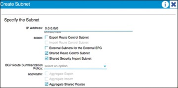
Figure 6-25 Shared Route Control and Shared Security Import Subnet Configuration
)
In the example in Figure 6-25, the Aggregate Shared Routes option is checked. This means that all routes will be marked as shared route control (in other words, all routes will be eligible for advertisement through this shared L3 Out connection).
At the individual tenant level, subnets defined under bridge domains should be marked as both Advertised Externally and Shared Between VRFs, as shown in Figure 6-26.
)
Figure 6-26 Subnet Scope Options
Transit Routing
The transit routing function in the Cisco ACI fabric enables the advertisement of routing information from one L3 Out connection to another, allowing full IP connectivity between routing domains through the Cisco ACI fabric.
To configure transit routing through the Cisco ACI fabric, you must mark the subnets in question with the Export Route Control option when configuring external networks under the L3 Out configuration. Figure 6-27 shows an example.
)
Figure 6-27 Export Route Control Operation
In the example in Figure 6-27, the desired outcome is for subnet 60.1.1.0/24 (which has been received from Router 1) to be advertised through the Cisco ACI fabric to Router 2. To achieve this, the 60.1.1.0/24 subnet must be defined on the second L3 Out and marked as an export route control subnet. This will cause the subnet to be redistributed from MP-BGP to the routing protocol in use between the fabric and Router 2.
It may not be feasible or scalable to define all possible subnets individually as export route control subnets. It is therefore possible to define an aggregate option that will mark all subnets with export route control. Figure 6-28 shows an example.
)
Figure 6-28 Aggregate Export Option
In the example in Figure 6-28, there are a number of subnets received from Router 1 that should be advertised to Router 2. Rather than defining each subnet individually, the administrator can define the 0.0.0.0/0 subnet and mark it with both export route control and the Aggregate export option. This option instructs the fabric that all transit routes should be advertised from this L3 Out. Note that the Aggregate export option does not actually configure route aggregation or summarization; it is simply a method to specify all possible subnets as exported routes. Note also that this option works only when the subnet is 0.0.0.0/0; the option will not be available when you’re configuring any subnets other than 0.0.0.0/0.
In some scenarios, you may need to export static routes between L3 Out connections, as shown in Figure 6-29.
)
Figure 6-29 Exporting Static Routes
In the example in Figure 6-29, a static route to 60.1.1.0 is configured on the left L3 Out. If you need to advertise the static route through the right L3 Out, the exact subnet must be configured and marked with export route control. A 0.0.0.0/0 aggregate export subnet will not match the static route.
Finally, note that route export control affects only routes that have been advertised to the Cisco ACI fabric from outside. It has no effect on subnets that exist on internal bridge domains.
Route maps are used on the leaf nodes to control the redistribution from BGP to the L3 Out routing protocol. For example, in the output in Example 6-1, a route map is used for controlling the redistribution between BGP and OSPF.
Example 6-1 Controlling Redistribution with a Route Map
Leaf-101# show ip ospf vrf tenant-1:vrf-1
Routing Process default with ID 6.6.6.6 VRF tenant-1:vrf-1
Stateful High Availability enabled
Supports only single TOS(TOS0) routes
Supports opaque LSA
Table-map using route-map exp-ctx-2818049-deny-external-tag
Redistributing External Routes from
static route-map exp-ctx-st-2818049

direct route-map exp-ctx-st-2818049

bgp route-map exp-ctx-proto-2818049

eigrp route-map exp-ctx-proto-2818049
Further analysis of the route map shows that prefix lists are used to specify the routes to be exported from the fabric, as demonstrated in Example 6-2.
Example 6-2 Using Prefix Lists to Specify Which Routes to Export
Leaf-101# show route-map exp-ctx-proto-2818049
route-map exp-ctx-proto-2818049, permit, sequence 7801
Match clauses:
ip address prefix-lists: IPv6-deny-all IPv4-proto16389-2818049-exc-ext-inferred-
  exportDST
  Set clauses:
    tag 4294967295
route-map exp-ctx-proto-2818049, permit, sequence 9801
Match clauses:
ip address prefix-lists: IPv6-deny-all IPv4-proto49160-2818049-agg-ext-inferred-
  exportDST
  Set clauses:
    tag 4294967295
Finally, analysis of the prefix list shows the exact routes that were marked as export route control in the L3 Out connection, as demonstrated in Example 6-3.
Example 6-3 Routes Marked as Export Route
Leaf-101# show ip prefix-list IPv4-proto16389-2818049-exc-ext-inferred-exportDST ip
  prefix-list IPv4-proto16389-2818049-exc-ext-inferred-exportDST: 1 entries
seq 1 permit 70.1.1.0/24
Supported Combinations for Transit Routing
Some limitations exist on the supported transit routing combinations through the fabric. In other words, transit routing is not possible between all the available routing protocols. For example, at the time of this writing, transit routing is not supported between two connections if one is running EIGRP and the other is running BGP.
The latest matrix showing supported transit routing combinations is available at the following link:
Loop Prevention in Transit Routing Scenarios
When the Cisco ACI fabric advertises routes to an external routing device using OSPF or EIGRP, all advertised routes are tagged with the number 4294967295 by default. For loop-prevention purposes, the fabric will not accept routes inbound with the 4294967295 tag. This may cause issues in some scenarios where tenants and VRFs are connected together through external routing devices, or in some transit routing scenarios such as the example shown in Figure 6-30.
)
Figure 6-30 Loop Prevention with Transit Routing
In the example in Figure 6-30, an external route (30.1.0.0/16) is advertised in Cisco ACI Tenant 2, which is acting as a transit route. This route is advertised to the firewall through the second L3 Out, but with a route tag of 4294967295. When this route advertisement reaches Cisco ACI Tenant 1, it is dropped due to the tag.
To avoid this situation, the default route tag value should be changed under the tenant VRF, as shown in Figure 6-31.
)
Figure 6-31 Changing Route Tags
WAN Integration
In Release 2.0 of the Cisco ACI software, a new option for external Layer 3 connectivity is available, known as Layer 3 Ethernet Virtual Private Network over Fabric WAN (for more information, see the document “Cisco ACI Fabric and WAN Integration with Cisco Nexus 7000 Series Switches and Cisco ASR Routers White Paper” at Cisco.com [http://tinyurl.com/ACIFabNex]).
This option uses a single BGP session from the Cisco ACI spine switches to the external WAN device. All tenants are able to share this single connection, which dramatically reduces the number of tenant L3 Out connections required.
Additional benefits of this configuration are that the controller handles all of the fabric-facing WAN configuration per tenant. Also, when this configuration is used with multiple fabrics or multiple pods, host routes will be shared with the external network to facilitate optimal routing of inbound traffic to the correct fabric and resources. The recommended approach is that all WAN integration routers have neighbor relationships with ACI fabrics (spines) at each site.
Figure 6-32 shows Layer 3 EVPN over fabric WAN.
Note that Layer 3 EVPN connectivity differs from regular tenant L3 Out connectivity in that the physical connections are formed from the spine switches rather than leaf nodes. Layer 3 EVPN requires an L3 Out connection to be configured in the Infra tenant. This L3 Out connection will be configured to use BGP and to peer with the external WAN device. The BGP peer will be configured for WAN connectivity under the BGP peer profile, as shown in Figure 6-33.
)
Figure 6-32 Layer 3 EVPN over Fabric WAN
)
Figure 6-33 BGP WAN Connectivity Configuration
The L3 Out connection must also be configured with a provider label. Each individual tenant will then be configured with a local L3 Out connection configured with a consumer label, which will match the provider label configured on the Infra L3 Out connection.
Design Recommendations for Multitenant External Layer 3 Connectivity
In a small-to-medium-size environment (up to a few hundred tenants) and in environments where the external routing devices do not support EVPN connectivity, it is acceptable and recommended to use individual L3 Out connections per tenant. This is analogous to the use of VRF-lite in traditional environments, where each routed connection is trunked as a separate VLAN and subinterface on the physical links from the leaf nodes to the external device.
In a larger environment, the L3 Out per-tenant approach may not scale to the required level. For example, the total number of L3 Out connections for a given Cisco ACI fabric is 400 at press time. In that case, the recommended approach is to use Layer 3 EVPN over fabric WAN to achieve multitenant Layer 3 connectivity from the fabric. This approach will provide a greater scale and is also preferred over the shared L3 Out approach described earlier in this document. Finally, if your organization will be leveraging ACI in multiple fabric or multiple pod topologies for disaster recovery or active/active scenarios, where path optimization is a concern, Layer 3 EVPN over fabric WAN should be a consideration.
Quality of Service
The ACI fabric will transport a multitude of applications and data. The applications your data center supports will no doubt have different levels of service assigned to these applications based on their criticality to the business. Data center fabrics must provide secure, predictable, measurable, and sometimes guaranteed services. Achieving the required Quality of Service (QoS) by effectively managing the priority of your organization’s applications on the fabric is important when deploying a successful end-to-end business solution. Thus, QoS is the set of techniques to manage data center fabric resources.
As with normal QoS, QoS within ACI deals with classes and markings to place traffic into these classes. Each QoS class represents a Class of Service, and is equivalent to “qos-group” in traditional NXOS. Each Class of Service maps to a Queue or set of Queues in Hardware. Each Class of Service can be configured with various options, including a scheduling policy (Weighted Round Robin or Strict Priority, WRR being default), min buffer (guaranteed buffer), and/or a max buffer (static or dynamic, dynamic being default).
These classes are configured at a system level, and are therefore called system classes. At the system level, there are six supported classes, including three user-defined classes and three reserved classes which are not configurable by the user.
User-Defined Classes
As mentioned above, there is a maximum of three user-defined classes within ACI. The three classes are:
Level1
Level2
Level3 (always enabled & equivalent to best-effort class in traditional NXOS)
All of the QoS classes are configured for all ports in the fabric. This includes both the host-facing ports and the fabric or uplink ports. There is no per-port configuration of QoS classes in ACI as with some of the other Cisco technologies. Only one of these user-defined classes can be set as a strict priority class at any time.
Reserved Classes
As mentioned above, there are three reserved classes that are not configurable by the user:
Insieme Fabric Controller (IFC) Class — All APIC-originated or -destined traffic is classified into this class. This class has the following characteristics. It is a strict priority class. When Flowlet prioritization mode is enabled, prioritized packets use this class.
Control Class (Supervisor Class) — This class has the following characteristics. It is a strict priority class. All supervisor-generated traffic is classified into this class. All control traffic, such as protocol packets, uses this class.
SPAN Class — All SPAN and ERSPAN traffic is classified into this class. This class has the following characteristics. It is a best effort class. This class uses a congestion algorithm of Deficit Weighted Round Robin (DWRR) and least possible weight parameters. This class can be starved.
Classification and Marking
When Quality of Service is being used in ACI to classify packets, packets are classified using layer 2 Dot1p Policy, layer 3 Differentiated Services Code Point (DSCP) policy, or Contracts. The policies used to configure and apply DSCP and Dot1p are configured at the EPG level using a “Custom QoS Policy”. In the “Custom QoS Policy” a range of DSCP or Dot1p values will be used to create a rule and map these values to a DSCP target. If both Dot1p and DSCP policy are configured within an EPG, the DSCP policy takes precedence. The order in which one QoS policy takes precedence over another is based on the following list starting with the highest priority and ending with the lowest:
Zone rule
EPG-based DSCP policy
EPG-based Dot1p Policy
EPG-based default qos-grp
A second example of this hierarchy would be if a packet matches both a zone rule with a QoS action and an EPG-based policy. The zone rule action will take presidence. If there is no QoS policy configured for an EPG, all traffic will fall into the default QoS group (qos-grp).
QoS Configuration in ACI
Once you understand classification and marking, configuration of QoS in ACI is straightforward. Within the APIC GUI, there are three main steps to configure your EPG to use QoS:
Configure Global QoS Class parameters — The configuration performed here allows administrators to set the properties for the individual class.
Configure Custom QoS Policy within the EPG (if necessary) — This configuration lets administrators specify what traffic to look for and what to do with that traffic.
Assign QoS Class and/or Custom QoS Class (if applicable) to your EPG.
Contracts can also be used to classify and mark traffic between EPGs. For instance, your organization may have the requirement to have traffic marked specifically with DSCP values within the ACI fabric so these markings are seen at egress of the ACI fabric, allowing appropriate treatment on data center edge devices. The high-level steps to configure QoS marking using contracts are as follows:
ACI Global QoS policies should be enabled.
Create filters — Any TCP/UDP port can be used in the filter for later classification in the contract subject. The filters that are defined will allow for separate marking and classification of traffic based on traffic type. For example, SSH traffic can be assigned higher priority than other traffic. Two filters would have to be defined, one matching SSH, and one matching all IP traffic.
Define a Contract to be provided and consumed.
Add subjects to the contract.
Specify the directionality (bidirectional or one-way) of the subject and filters
Add filters to the subject
Assign a QoS class
Assign a target DSCP
Repeat as necessary for additional subjects and filters.
Traffic matching on the filter will now be marked with the specified DSCP value per subject.
Multicast
Many enterprise data center applications require IP multicast support and rely on multicast packet delivery across Layer 3 boundaries to provide necessary services and functions.
Previous versions of the ACI fabric were limited to constraining IPv4 multicast at Layer 2 within each bridge domain based on the Internet Group Management Protocol (IGMP) snooping state. Any inter–bridge domain multicast routing, as well as multicast routing in to or out of the Cisco ACI fabric, requires a Protocol-Independent Multicast (PIM) router external to the fabric to perform those functions.
With the introduction of APIC 2.0(1), along with the Cisco Nexus 9300 EX leaf-switch platforms based on the leaf-and-spine engine (LSE) application-specific integrated circuit (ASIC), the Cisco ACI fabric itself provides distributed Layer 3 IP multicast routing between bridge domains, reducing or eliminating the need for external multicast routers.
The following multicast protocols are now supported with the 2.0(1) release:
PIM any-source multicast (PIM-ASM)
PIM source-specific multicast (PIM-SSM)
Static rendezvous point (RP), Auto-RP, and bootstrap router (BSR) for RP-to-group mapping
Native Layer 3 IP multicast forwarding between bridge domains in the Cisco ACI fabric requires Cisco Nexus 9300 EX platform leaf switches, built with the LSE ASIC. Earlier leaf-switch platforms do not have the hardware capability to perform inter–bridge domain multicast routing and require an external multicast router to perform this function.
Multicast Best-Practice Recommendations
This section describes recommended best practices for three possible Cisco ACI fabric deployment scenarios. The scenarios differ in the capabilities of the leaf-switch platforms (see Figure 6-34):
All leaf switches are first-generation switches that do not use the Cisco Nexus EX platform. They are based on the application leaf engine (ALE) ASICs and require external multicast routers to perform inter–bridge domain and entry and exit multicast routing.
All leaf switches are second-generation Cisco Nexus EX platform switches. They are based on the LSE ASIC and support native inter–bridge domain Layer 3 multicast routing as well as entry and exit multicast routing at the border leaf.
The leaf switches are a hybrid of some Cisco Nexus EX platform leaf switches and some leaf switches that do not use the EX platform.
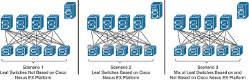
Figure 6-34 Three Possible Multicast Deployment Scenarios
)
Scenario 1: Leaf Switches Not Based on Cisco Nexus EX Platform
The best-practice recommendation is integration of external multicast routers with the Cisco ACI fabric to support inter–bridge domain and entry and exit IP multicast routing, as shown in Figure 6-35.
)
Figure 6-35 Scenario 1: External PIM Router
Scenario 2: Leaf Switches Based on Cisco Nexus EX Platform
For Cisco ACI fabrics in which all leaf switches are based on the EX platform (see Figure 6-36), the best-practice recommendation is to enable native IP multicast routing in the Cisco ACI fabric. This configuration uses the latest technology generation, simplifies the network design, and simplifies IP multicast routing configuration and management. Documentation outlining how to enable multicast in the ACI fabric can be found in “Cisco ACI and Layer 3 Multicast” at Cisco.com (http://tinyurl.com/ACIL3Multi).
)
Figure 6-36 Scenario 2: Native Layer 3 Multicast
Scenario 3: Hybrid Fabric with Leaf Switches Both Based on and Not Based on Cisco Nexus EX Platform
In a hybrid environment (see Figure 6-37), in which some of the leaf switches are not based on the EX platform and others are based on the EX platform, the best-practice recommendation is to continue to use an external router to perform multicast routing. Although it is technically possible to combine native multicast routing on EX platform leaf switches for some bridge domains with external multicast routing, for other bridge domains, design, configuration, and management become increasingly complex and error-prone.
)
Figure 6-37 Scenario 3: Hybrid Leaf Capability
Furthermore, when you enable multicast routing in the APIC, you enable it at the tenant VRF level and then, optionally, at the bridge domain level. For example, if you have a tenant VRF instance with multiple bridge domains, you can enable Layer 3 multicast on all those bridge domains or only on a subset. In either case, you must first enable multicast at the VRF level in order to enable multicast routing on one or more bridge domains within that VRF instance (see Figure 6-38).
)
Figure 6-38 Layer 2 Versus Layer 3 Multicast for Tenant VRF Instances and Bridge Domains
As shown in Figure 6-38, Tenant VRF1 has Layer 3 multicast enabled for the VRF instance and for all the bridge domains in that VRF instance. Leaf switches can route multicast traffic between any of those bridge domains, and border leaf switches can route traffic in to and out of the Cisco ACI fabric for those bridge domains.
Tenant VRF2 has Layer 3 multicast enabled for the VRF instance, but not all the bridge domains have Layer 3 multicast enabled. Leaf switches can route multicast traffic between BD1 and BD2, but not into BD3. BD3 may or may not have Layer 2 multicast enabled (Layer 2 multicast with IGMP snooping in the bridge domain is enabled by default but can be disabled). If it does, IP multicast traffic can be constrained within the bridge domain, but it cannot be routed to other bridge domains or in to and out of the fabric.
Tenant VRF3 does not have Layer 3 multicast enabled, but may have Layer 2 multicast enabled for some or all the bridge domains. The leaf switches perform no inter–bridge domain routing in this case. An external PIM router must provide any inter–bridge domain multicast routing.
Multicast Configuration Overview
In this section we examine the minimum configuration needed to support both PIM-ASM and PIM-SSM.
Minimum Multicast Configuration: PIM-ASM
The minimum configuration for basic Layer 3 PIM-ASM requires you to enable multicast for the VRF instance, add one or more bridge domains on the Interfaces configuration subtab, and define a static rendezvous point address in the Rendezvous Points subtab. The PIM rendezvous point must be located outside the Cisco ACI fabric. Verify that the rendezvous point IP address is reachable from inside the fabric.
The industry best practice for rendezvous point configuration is AnycastRP using Multicast Source Discovery Protocol (MSDP), with static rendezvous point address configuration. The Layer 3 multicast configuration in the Cisco ACI fabric provides support for specifying a static rendezvous point address for PIM-ASM, as well as dynamic options for disseminating rendezvous point information such as BSR and Auto-RP.
Minimum Multicast Configuration: PIM-SSM
The minimum configuration for basic Layer 3 PIM-SSM requires you to enable multicast for the VRF instance, add one or more bridge domains on the Interfaces configuration subtab, and enable IGMPv3 processing on those bridge domains (PIM-SSM does not require a rendezvous point).
Summary
The Cisco ACI solution allows you to use standard Layer 3 technologies to connect to external networks. These external networks can be Layer 3 connections to an existing network, WAN routers, firewalls, mainframes, or any other Layer 3 device.
This chapter covered the following topics:
L3 physical connectivity considerations
Static and supported routing protocols
Access control in and out of the fabric through the use of contracts
Multitenant routing considerations
WAN integration
Quality of Service
Multicast best-practice recommendations
No matter what you are connecting to, ACI has the ability to provide reliable and high-performance connectivity to meet simple or complex application and data center needs.