In this sample chapter from Scaling Networks v6 Companion Guide, learn strategies that can be used to systematically design a highly functional network, such as the hierarchical network design model and appropriate device selections.
Objectives
Upon completion of this chapter, you will be able to answer the following questions:
What are the appropriate hierarchical network designs for small businesses?
What are the considerations for designing a scalable network?
What switch hardware features are appropriate to support network requirements in small to medium-sized business networks?
What types of routers are available for small to medium-sized business networks?
What are the basic configuration settings for a Cisco IOS device?
Key Terms
This chapter uses the following key terms. You can find the definitions in the Glossary.
mission-critical services
enterprise network
network operations center (NOC)
hierarchical design model
access layer
distribution layer
core layer
collapsed core design
multilayer switch
Redundant links
link aggregation
redundancy
Spanning Tree Protocol (STP)
failure domain
wireless access point (AP)
building switch block
departmental switch block
EtherChannel
port channel interface
load balancing
Open Shortest Path First (OSPF)
Enhanced Interior Gateway Routing Protocol (EIGRP)
link-state routing protocol
single-area OSPF
multiarea OSPF
distance vector routing protocol
form factor
Power over Ethernet (PoE)
campus LAN switch
cloud-managed switch
data center switch
service provider switch
virtual networking switch
fixed configuration
modular configuration
stackable configuration
rack unit
supervisor engine
port density
small form-factor pluggable (SFP)
forwarding rates
wire speed
application-specific integrated circuits (ASIC)
branch router
network edge router
service provider router
Cisco Internetwork Operating System (IOS)
IOS image
out-of-band management
in-band management
PuTTY
TeraTerm
Introduction (1.0.1.1)
There is a tendency to discount a network as just simple plumbing, to think that all you have to consider is the size and the length of the pipes or the speeds and feeds of the links, and to dismiss the rest as unimportant. Just as the plumbing in a large stadium or high rise has to be designed for scale, purpose, redundancy, protection from tampering or denial of operation, and the capacity to handle peak loads, a network requires similar consideration. As users depend on a network to access the majority of the information they need to do their jobs and to transport their voice or video with reliability, the network must be able to provide resilient, intelligent transport.
As a business grows, so does its networking requirements. Businesses rely on the network infrastructure to provide mission-critical services. Network outages can result in lost revenue and lost customers. Network designers must design and build an enterprise network that is scalable and highly available.
The campus local area network (LAN) is the network that supports devices people use within a location to connect to information. The campus LAN can be a single switch at a small remote site up to a large multi-building infrastructure, supporting classrooms, office space, and similar places where people use their devices. The campus design incorporates both wired and wireless connectivity for a complete network access solution.
This chapter discusses strategies that can be used to systematically design a highly functional network, such as the hierarchical network design model and appropriate device selections. The goals of network design are to limit the number of devices impacted by the failure of a single network device, provide a plan and path for growth, and create a reliable network.
Class Activity 1.0.1.2: Network by Design
Refer to Scaling Networks v6 Labs & Study Guide and the online course to complete this activity.
Your employer is opening a new branch office. You have been reassigned to the site as the network administrator, and your job will be to design and maintain the new branch network. The network administrators at the other branches used the Cisco three-layer hierarchical model when designing their networks. You decide to use the same approach. To get an idea of what using the hierarchical model can do to enhance the design process, you research the topic.
Campus Wired LAN Designs (1.1)
Enterprise networks come in all sizes. There are small networks consisting of a few hosts, medium-sized networks consisting of a few hundred hosts, and large networks consisting of thousands of hosts. Besides the number of hosts these networks must support, consideration must be given to the applications and services that must be supported to meet the organizational goals.
Fortunately, proven methods are available to design all types of networks. The Cisco Enterprise Architecture is an example of a proven campus network design.
In this section, you will learn why it is important to design a scalable hierarchical network.
Cisco Validated Designs (1.1.1)
Networks must be scalable, which means they must be able to accommodate an increase or a decrease in size. The focus of this topic is to discover how the hierarchical design model is used to help accomplish this task.
The Need to Scale the Network (1.1.1.1)
Businesses increasingly rely on their network infrastructure to provide mission-critical services. As businesses grow and evolve, they hire more employees, open branch offices, and expand into global markets. These changes directly affect the requirements of a network.
The LAN is the networking infrastructure that provides access to network communication services and resources for end users and devices spread over a single floor or building. A campus network is created by interconnecting a group of LANs that are spread over a small geographic area.
Campus network designs include small networks that use a single LAN switch, up to very large networks with thousands of connections. For example, in Figure 1-1, the company is located in a single location with one connection to the Internet.
)
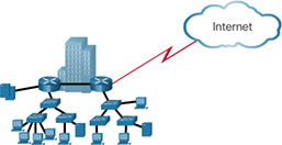
Figure 1-1 A Small, Single-Location Company
In Figure 1-2, the company grows to multiple locations in the same city.
)
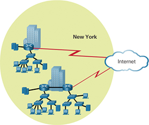
Figure 1-2 The Company Grows to Multiple Locations in the Same City
In Figure 1-3, the company continues to grow and expands to more cities. It also hires and connects teleworkers.
)
Figure 1-3 Enterprise Grows to Multiple Cities and Adds Teleworkers
In Figure 1-4, the company expands to other countries and centralizes management in a network operations center (NOC).
)
Figure 1-4 Enterprise Becomes Global and Centralizes Network Operations
In addition to supporting physical growth, a network must also support the exchange of all types of network traffic, including data files, email, IP telephony, and video applications for multiple business units.
Specifically, all enterprise networks must:
Support mission-critical services and applications
Support converged network traffic
Support diverse business needs
Provide centralized administrative control
To help campus LANs meet these requirements, a hierarchical design model is used.
Hierarchical Design Model (1.1.1.2)
The campus wired LAN enables communications between devices in a building or group of buildings, as well as interconnection to the WAN and Internet edge at the network core.
Early networks used a flat or meshed network design, in which large numbers of hosts were connected in the same network. Changes affected many hosts in this type of network architecture.
Campus wired LANs now use a hierarchical design model that divides network design into modular groups or layers. Dividing (or breaking) the network design into layers enables each layer to implement specific functions. This simplifies the network design and the deployment and management of the network.
A hierarchical LAN design consists of the following three layers, as shown in Figure 1-5:
Access layer
Distribution layer
Core layer
)
Figure 1-5 Hierarchical Design Model
Each layer is designed to meet specific functions.
The access layer provides endpoints and users direct access to the network. The distribution layer aggregates access layers and provides connectivity to services. Finally, the core layer provides connectivity between distribution layers for large LAN environments. User traffic is initiated at the access layer and passes through the other layers if the functionality of those layers is required.
Medium-sized to large enterprise networks commonly implement the three-layer hierarchical design model. However, some smaller enterprise networks may implement a two-tier hierarchical design, referred to as a collapsed core design. In a two-tier hierarchical design, the core and distribution layers are collapsed into one layer, reducing cost and complexity, as shown in Figure 1-6.
)
Figure 1-6 Collapsed Core
In flat or meshed network architectures, changes tend to affect a large number of systems. Hierarchical design helps constrain operational changes to a subset of the network, which makes it easy to manage and improves resiliency. Modular structuring of the network into small, easy-to-understand elements also facilitates resiliency via improved fault isolation.
Expanding the Network (1.1.2)
Networks must be scalable, which means they must be able to accommodate an increase or a decrease in size. The focus of this topic is to discover how the hierarchical design model is used to help accomplish this task.
Design for Scalability (1.1.2.1)
To support a large, medium, or small network, the network designer must develop a strategy to enable the network to be available and to scale effectively and easily. Included in a basic network design strategy are the following recommendations:
Use expandable, modular equipment or clustered devices that can be easily upgraded to increase capabilities. Device modules can be added to the existing equipment to support new features and devices without requiring major equipment upgrades. Some devices can be integrated in a cluster to act as one device to simplify management and configuration.
Design a hierarchical network to include modules that can be added, upgraded, and modified as necessary, without affecting the design of the other functional areas of the network. For example, you might create a separate access layer that can be expanded without affecting the distribution and core layers of the campus network.
Create an IPv4 or IPv6 address strategy that is hierarchical. Careful address planning eliminates the need to re-address the network to support additional users and services.
Use a router or multilayer switch to limit broadcasts and filter other undesirable traffic from the network. Use Layer 3 devices to filter and reduce traffic to the network core.
As shown in Figure 1-7, more advanced network design requirements include:
)
Figure 1-7 Design for Scalability
A. Redundant links—Implementing redundant links in the network between critical devices and between access layer and core layer devices.
B. Link aggregation—Implementing multiple links between equipment, with either link aggregation (EtherChannel) or equal-cost load balancing, to increase bandwidth. Combining multiple Ethernet links into a single, load-balanced EtherChannel configuration increases the available bandwidth. EtherChannel implementations can be used when budget restrictions prohibit purchasing high-speed interfaces and fiber runs.
C. Scalable routing protocols—Using a scalable routing protocol such as multiarea OSPF and implementing features within that routing protocol to isolate routing updates and minimize the size of the routing table.
D. Wireless mobility—Implementing wireless connectivity to allow for mobility and expansion.
Planning for Redundancy (1.1.2.2)
For many organizations, the availability of the network is essential to supporting business needs. Redundancy is an important part of network design for preventing disruption of network services by minimizing the possibility of a single point of failure. One method of implementing redundancy is to install duplicate equipment and provide failover services for critical devices.
Another method of implementing redundancy is using redundant paths, as shown in Figure 1-8. Redundant paths offer alternate physical paths for data to traverse the network. Redundant paths in a switched network support high availability. However, due to the operation of switches, redundant paths in a switched Ethernet network may cause logical Layer 2 loops. For this reason, Spanning Tree Protocol (STP) is required.
)
Figure 1-8 LAN Redundancy
STP eliminates Layer 2 loops when redundant links are used between switches. It does this by providing a mechanism for disabling redundant paths in a switched network until the path is necessary, such as when failures occur. STP is an open standard protocol used in a switched environment to create a loop-free logical topology.
Chapter 3, “STP,” provides more details about LAN redundancy and the operation of STP.
Failure Domains (1.1.2.3)
A well-designed network not only controls traffic but also limits the size of failure domains. A failure domain is the area of a network that is impacted when a critical device or network service experiences problems.
The function of the device that initially fails determines the impact of a failure domain. For example, a malfunctioning switch on a network segment normally affects only the hosts on that segment. However, if the router that connects this segment to others fails, the impact is much greater.
The use of redundant links and reliable enterprise-class equipment minimizes the chance of disruption in a network. Smaller failure domains reduce the impact of a failure on company productivity. They also simplify the troubleshooting process, thereby shortening the downtime for all users.
Figure 1-9 shows an example of the failure domain for a router.
)
Figure 1-9 Failure Domain—Router
Figure 1-10 shows an example of the failure domain for a switch.
)
Figure 1-10 Failure Domain—Switch
Figure 1-11 shows an example of the failure domain for a wireless access point (AP).
)
Figure 1-11 Failure Domain—Wireless Access Point
Because a failure at the core layer of a network can have a potentially large impact, the network designer often concentrates on efforts to prevent failures. These efforts can greatly increase the cost of implementing the network.
In the hierarchical design model, it is easiest and usually least expensive to control the size of a failure domain in the distribution layer. Limiting the size of failure domains in the distribution layer confines network errors to a smaller area and thereby affects fewer users. When using Layer 3 devices at the distribution layer, every router functions as a gateway for a limited number of access layer users.
Routers or multilayer switches are usually deployed in pairs, with access layer switches evenly divided between them. This configuration is referred to as a building switch block or a departmental switch block. Each switch block acts independently of the others. As a result, the failure of a single device does not cause the network to go down. Even the failure of an entire switch block does not affect a significant number of end users.
Increasing Bandwidth (1.1.2.4)
In hierarchical network design, some links between access and distribution switches may need to process a greater amount of traffic than other links. As traffic from multiple links converges onto a single, outgoing link, it is possible for that link to become a bottleneck.
Link aggregation allows an administrator to increase the amount of bandwidth between devices by creating one logical link by grouping several physical links together. EtherChannel is a form of link aggregation used in switched networks, as shown in Figure 1-12.
)
Figure 1-12 Advantages of EtherChannel
EtherChannel uses the existing switch ports. Therefore, additional costs to upgrade the link to a faster and more expensive connection are not necessary. The EtherChannel is seen as one logical link, using an EtherChannel interface.
On a Cisco Catalyst switch, an EtherChannel is configured as a port channel interface. Most configuration tasks are done on the port channel interface instead of on each individual port to ensure configuration consistency throughout the links.
Finally, the EtherChannel configuration takes advantage of load balancing between links that are part of the same EtherChannel, and depending on the hardware platform, one or more load balancing methods can be implemented.
EtherChannel operation and configuration are covered in more detail Chapter 4, “EtherChannel and HSRP.”
Expanding the Access Layer (1.1.2.5)
A network must be designed to be able to expand network access to individuals and devices as needed. An increasingly important aspect of extending access layer connectivity is wireless connectivity. Providing wireless connectivity offers many advantages, such as increased flexibility, reduced costs, and the ability to grow and adapt to changing network and business requirements.
To communicate wirelessly, end devices require a wireless network interface card (NIC) that incorporates a radio transmitter/receiver and the required software driver to make it operational. In addition, a wireless router or a wireless access point (AP) is required for users to connect, as shown in Figure 1-13.
)
Figure 1-13 Wireless LANs
Implementing a wireless network involves many considerations, such as the types of wireless devices to use, wireless coverage requirements, interference considerations, and security considerations.
Fine-tuning Routing Protocols (1.1.2.6)
Advanced routing protocols, such as Open Shortest Path First (OSPF) and Enhanced Interior Gateway Routing Protocol (EIGRP), are used in large networks.
A link-state routing protocol such as OSPF, as shown in Figure 1-14, works well for larger hierarchical networks where fast convergence is important.
)
Figure 1-14 Single-Area OSPF
OSPF routers establish and maintain neighbor adjacency or adjacencies with other connected OSPF routers. When routers initiate an adjacency with neighbors, an exchange of link-state updates begins. Routers reach a FULL state of adjacency when they have synchronized views on their link-state database. With OSPF, link-state updates are sent when network changes occur. Single-area OSPF configuration and concepts are covered in Chapter 8, “Single-Area OSPF.”
In addition, OSPF supports a two-layer hierarchical design, referred to as multiarea OSPF, as shown in Figure 1-15.
All multiarea OSPF networks must have an Area 0, also called the backbone area. Non-backbone areas must be directly connected to area 0. Chapter 9, “Multiarea OSPF,” introduces the benefits, operation, and configuration of multiarea OSPF. Chapter 10, “OSPF Tuning and Troubleshooting,” covers more advanced features of OSPF.
)
Figure 1-15 Multiarea OSPF
Another popular routing protocol for larger networks is EIGRP. Cisco developed EIGRP as a proprietary distance vector routing protocol with enhanced capabilities. Although configuring EIGRP is relatively simple, the underlying features and options of EIGRP are extensive and robust. For example, EIGRP uses protocol-dependent modules (PDM), which enable support for IPv4 and IPv6 routing tables, as shown in Figure 1-16.
)
Figure 1-16 EIGRP Protocol-Dependent Modules (PDM)
EIGRP contains many features that are not found in any other routing protocols. It is an excellent choice for large multiprotocol networks that use primarily Cisco devices.
Chapter 6, “EIGRP,” introduces the operation and configuration of the EIGRP routing protocol, and Chapter 7, “EIGRP Tuning and Troubleshooting,” covers some of the more advanced configuration options of EIGRP.

Activity 1.1.2.7: Identify Scalability Terminology
Refer to the online course to complete this activity.
Selecting Network Devices (1.2)
Switches and routers are core network infrastructure devices. Therefore, selecting them appears to be a fairly simple task. However, many different models of switches and routers are available. Different models provide various numbers of ports, different forwarding rates, and unique feature support.
In this section, you will learn how to select network devices based on feature compatibility and network requirements.
Switch Hardware (1.2.1)
Various types of switch platforms are available. Each platform differs in terms of physical configuration and form factor, the number of ports, and the features supported, including Power over Ethernet (PoE) and routing protocols.
The focus of this topic is on how to select the appropriate switch hardware features to support network requirements in small to medium-sized business networks.
Switch Platforms (1.2.1.1)
When designing a network, it is important to select the proper hardware to meet current network requirements, as well as allow for network growth. Within an enterprise network, both switches and routers play a critical role in network communication.
There are five categories of switches for enterprise networks, as shown in Figure 1-17:
)
Figure 1-17 Switch Platforms
Campus LAN switch—To scale network performance in an enterprise LAN, there are core, distribution, access, and compact switches. These switch platforms vary from fanless switches with eight fixed ports to 13-blade switches supporting hundreds of ports. Campus LAN switch platforms include the Cisco 2960, 3560, 3650, 3850, 4500, 6500, and 6800 Series.
Cloud-managed switch—The Cisco Meraki cloud-managed access switches enable virtual stacking of switches. They monitor and configure thousands of switch ports over the web, without the intervention of onsite IT staff.
Data center switch—A data center should be built based on switches that promote infrastructure scalability, operational continuity, and transport flexibility. The data center switch platforms include the Cisco Nexus Series switches and the Cisco Catalyst 6500 Series switches.
Service provider switch—Service provider switches fall under two categories: aggregation switches and Ethernet access switches. Aggregation switches are carrier-grade Ethernet switches that aggregate traffic at the edge of a network. Service provider Ethernet access switches feature application intelligence, unified services, virtualization, integrated security, and simplified management.
Virtual networking switch—Networks are becoming increasingly virtualized. Cisco Nexus virtual networking switch platforms provide secure multitenant services by adding virtualization intelligence technology to the data center network.
When selecting switches, network administrators must determine the switch form factors. These include fixed configuration (Figure 1-18), modular configuration (Figure 1-19), or stackable configuration (Figure 1-20).
)
Figure 1-18 Fixed Configuration Switches
)
Figure 1-19 Modular Configuration Switches
)
Figure 1-20 Stackable Configuration Switches
The amount of space that a device occupies in a network rack is also an important consideration. Rack unit is a term used to describe the thickness of a rack-mountable network device. Defined in EIA-310, a unit (U) describes a device with a standard height of 4.45 centimeters (1 3/4 inches) and width of 48.26 centimeters (19 inches). For example, the fixed configuration switches shown in Figure 1-18 are all one rack unit (1U).
Besides the device form factor, other device selection considerations must be made. Table 1-1 describes some of these considerations.
Table 1-1 Considerations When Selecting Network Devices
| Consideration | Description |
|---|---|
| Cost | The cost of a switch depends on the number and speed of the interfaces, supported features, and expansion capability. |
| Port density | The port density describes how many ports are available on the switch. Network switches must support the appropriate number of devices on the network. |
| Port speed | The speed of the network connection is of primary concern to end users. |
| Forwarding rate | This rate defines the processing capabilities of a switch by rating how much data the switch can process per second. For instance, distribution layer switches should provide higher forwarding rates than access layer switches. |
| Size of frame buffers | Switches with large frame buffers are better able to store frames when there are congested ports to servers or other areas of the network. |
| PoE support | Power over Ethernet (PoE) is used to power access points, IP phones, security cameras, and even compact switches. Demand for PoE is increasing. |
| Redundant power | Some stackable and modular chassis-based switches support redundant power supplies. |
| Reliability | Switches should provide continuous access to the network. Therefore, select switches with reliable redundant features including redundant power supplies, fans, and supervisor engines. |
| Scalability | The number of users on a network typically grows over time. Therefore, select switches that provide the opportunity for growth. |
Some of these considerations are now described in more detail.
Port Density (1.2.1.2)
The port density of a switch refers to the number of ports available on a single switch. Figure 1-21 shows the port densities of three different switches.
)
Figure 1-21 Port Densities
Fixed configuration switches support a variety of port density configurations. The Cisco Catalyst 3850 24-port and 48-port switches are shown on the left in the figure. The 48-port switch has an option for 4 additional ports for small form-factor pluggable (SFP) devices. SFPs are small compact, hot-pluggable transceivers used on some switches to provide flexibility when choosing network media. SPF transceivers are available for copper and fiber Ethernet, Fibre Channel networks, and more.
Modular switches can support very high port densities through the addition of multiple switch port line cards. The modular Catalyst 6500 switch shown on the right in the figure can support in excess of 1000 switch ports.
Large networks that support many thousands of network devices require high-density modular switches to make the best use of space and power. Without high-density modular switches, a network would need many fixed configuration switches to accommodate the number of devices that need network access—and this approach can consume many power outlets and a lot of closet space.
A network designer must also consider the issue of uplink bottlenecks: A series of fixed configuration switches may consume many additional ports for bandwidth aggregation between switches, for the purpose of achieving target performance. With a single modular switch, bandwidth aggregation is less problematic because the backplane of the chassis can provide the necessary bandwidth to accommodate the devices connected to the switch port line cards.
Forwarding Rates (1.2.1.3)
Forwarding rates define the processing capabilities of a switch by rating how much data the switch can process per second. Switch product lines are classified by forwarding rates, as shown in Figure 1-22.
)
Forwarding rates are an important consideration when selecting a switch. If its forwarding rate is too low, a switch cannot accommodate full wire-speed communication across all of its switch ports. Wire speed is a term used to describe the data rate that each Ethernet port on the switch is capable of attaining. Data rates can be 100 Mb/s, 1 Gb/s, 10 Gb/s, or 100 Gb/s.
For example, a typical 48-port gigabit switch operating at full wire speed generates 48 Gb/s of traffic. If the switch supports a forwarding rate of only 32 Gb/s, it cannot run at full wire speed across all ports simultaneously.
Access layer switches are usually physically limited by their uplinks to the distribution layer. However, they typically do not need to operate at full wire speed. Therefore, less expensive, lower-performing switches can be used at the access layer. The more expensive, higher-performing switches can be used at the distribution and core layers, where the forwarding rate has a greater impact on network performance.
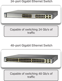
Figure 1-22 Forwarding Rate
Power over Ethernet (1.2.1.4)
PoE allows a switch to deliver power to a device over the existing Ethernet cabling. This feature can be used by IP phones and some wireless access points. Figure 1-23 shows PoE ports on various devices.
)
Figure 1-23 Power over Ethernet
PoE increases flexibility when installing wireless access points and IP phones because these devices can be installed anywhere that there is an Ethernet cable. Therefore, a network administrator should ensure that the PoE features are required because switches that support PoE are expensive.
The Cisco Catalyst 2960-C and 3560-C Series compact switches support PoE pass-through. PoE pass-through allows a network administrator to power PoE devices connected to the switch, as well as the switch itself, by drawing power from certain upstream switches. Figure 1-24 shows the PoE ports on a Cisco Catalyst 2960-C.
)
Figure 1-24 PoE Pass-through
Multilayer Switching (1.2.1.5)
Multilayer switches are typically deployed in the core and distribution layers of an organization’s switched network. Multilayer switches are characterized by their capability to build a routing table, support a few routing protocols, and forward IP packets at a rate close to that of Layer 2 forwarding. Multilayer switches often support specialized hardware, such as application-specific integrated circuits (ASIC). ASICs along with dedicated software data structures can streamline the forwarding of IP packets independently of the CPU.
There is a trend in networking toward a pure Layer 3 switched environment. When switches were first used in networks, none of them supported routing; now, almost all switches support routing. It is likely that soon all switches will incorporate a route processor because the cost is decreasing relative to other constraints.
As shown in Figure 1-25, the Catalyst 2960 switches illustrate the migration to a pure Layer 3 environment. With IOS versions prior to 15.x, these switches supported only one active switched virtual interface (SVI). With IOS 15.x, these switches now support multiple active SVIs. This means that a Catalyst 2960 switch can be remotely accessed via multiple IP addresses on distinct networks.
)
Figure 1-25 Cisco Catalyst 2960 Series Switches
Activity 1.2.1.6: Selecting Switch Hardware
Refer to the online course to complete this activity.

Packet Tracer 1.2.1.7: Comparing 2960 and 3560 Switches
In this activity, you will use various commands to examine three different switching topologies and compare the similarities and differences between the 2960 and 3560 switches. You will also compare the routing table of a 1941 router with a 3560 switch.
Router Hardware (1.2.2)
Various types of router platforms are available. Like switches, routers differ in physical configuration and form factor, the number and types of interfaces supported, and the features supported.
The focus of this topic is on how to describe the types of routers available to support network requirements in small to medium-sized business networks.
Router Requirements (1.2.2.1)
In the distribution layer of an enterprise network, routing is required. Without the routing process, packets cannot leave the local network.
Routers play a critical role in networking by determining the best path for sending packets. They connect multiple IP networks by connecting homes and businesses to the Internet. They are also used to interconnect multiple sites within an enterprise network, providing redundant paths to destinations. A router can also act as a translator between different media types and protocols. For example, a router can accept packets from an Ethernet network and re-encapsulate them for transport over a serial network.
Routers use the network portion of the destination IP address to route packets to the proper destination. They select an alternate path if a link or path goes down. All hosts on a local network specify the IP address of the local router interface in their IP configuration. This router interface is the default gateway. The ability to route efficiently and recover from network link failures is critical to delivering packets to their destination.
Routers also serve other beneficial functions, as shown in Figure 1-26:
Provide broadcast containment
Provide enhanced security
Connect remote locations
Group users logically by application or department
)
Figure 1-26 Router Functions
Cisco Routers (1.2.2.2)
As a network grows, it is important to select the proper routers to meet its requirements. As shown Figure 1-27, there are three categories of routers:
)
Figure 1-27 Router Platforms
Branch router—Branch routers optimize branch services on a single platform while delivering an optimal application experience across branch and WAN infrastructures. Maximizing service availability at the branch requires networks designed for 24x7x365 uptime. Highly available branch networks must ensure fast recovery from typical faults while minimizing or eliminating the impact on service, and they must provide simple network configuration and management.
Network edge router—Network edge routers enable the network edge to deliver high-performance, highly secure, and reliable services that unite campus, data center, and branch networks. Customers expect a high-quality media experience and more types of content than ever before. Customers want interactivity, personalization, mobility, and control for all content. Customers also want to access content anytime and anyplace they choose, over any device—whether at home, at work, or on the go. Network edge routers must deliver enhanced quality of service and nonstop video and mobile capabilities.
Service provider router—Service provider routers differentiate the service portfolio and increase revenues by delivering end-to-end scalable solutions and subscriber-aware services. Operators must optimize operations, reduce expenses, and improve scalability and flexibility to deliver next-generation Internet experiences across all devices and locations. These systems are designed to simplify and enhance the operation and deployment of service-delivery networks.
Router Hardware (1.2.2.3)
Routers are available in many form factors, as shown in Figure 1-28. Network administrators in an enterprise environment should be able to support a variety of routers, from a small desktop router to a rack-mounted or blade model.
)
Figure 1-28 A Sampling of Cisco Routers
Routers can also be categorized as fixed configuration or modular. With the fixed configuration, the desired router interfaces are built in. Modular routers come with multiple slots that allow a network administrator to change the interfaces on the router. For example, a Cisco 1941 router is a small modular router. It comes with two built-in Gigabit Ethernet RJ-45 interfaces, and it also has two slots that can accommodate many different network interface modules. Routers come with a variety of different interfaces, such as Fast Ethernet, Gigabit Ethernet, serial, and fiber-optic.
Visit www.cisco.com/c/en/us/products/routers/product-listing.html for a comprehensive list of Cisco routers.
Activity 1.2.2.4: Identify the Router Category
Refer to the online course to complete this activity.
Managing Devices (1.2.3)
Regardless of the form factor and the features each IOS device supports, it requires the Cisco Internetwork Operating System (IOS) to be operational.
The focus of this topic is on the Cisco IOS, how to manage it, and how to configure basic settings on Cisco IOS routers and switches.
Managing IOS Files and Licensing (1.2.3.1)
With such a wide selection of network devices to choose from in the Cisco product line, an organization can carefully determine the ideal combination to meet the needs of employees and customers.
When selecting or upgrading a Cisco IOS device, it is important to choose the proper IOS image with the correct feature set and version. The IOS image refers to the package of routing, switching, security, and other internetworking technologies integrated into a single multitasking operating system. When a new device is shipped, it comes preinstalled with the software image and the corresponding permanent licenses for the customer-specified packages and features.
For routers, beginning with Cisco IOS Software Release 15.0, Cisco modified the process to enable new technologies within the IOS feature sets, as shown in Figure 1-29.
)
Figure 1-29 Cisco IOS Software Release 15 Family
In this figure, EM (or Extended Maintenance) releases are released approximately every 16 to 20 months. The T releases are between EM releases and are ideal for the very latest features and hardware support before the next EM release becomes available.
In-Band versus Out-of-Band Management (1.2.3.2)
Regardless of the Cisco IOS network device being implemented, there are two methods for connecting a PC to that network device for configuration and monitoring tasks: out-of-band management and in-band management (see Figure 1-30).
)
Figure 1-30 In-Band versus Out-of-Band Configuration Options
Out-of-band management is used for initial configuration or when a network connection is unavailable. Configuration using out-of-band management requires:
A direct connection to a console or an AUX port
A terminal emulation client (such as PuTTY or TeraTerm)
In-band management is used to monitor and make configuration changes to a network device over a network connection. Configuration using in-band management requires:
At least one network interface on the device to be connected and operational
Telnet, SSH, HTTP, or HTTPS to access a Cisco device
Basic Router CLI Commands (1.2.3.3)
A basic router configuration includes the host name for identification, passwords for security, assignment of IP addresses to interfaces for connectivity, and basic routing.
Example 1-1 shows the commands entered to enable a router with RIPv2. Verify and save configuration changes by using the copy running-config startup-config command.
Example 1-1 Enabling a Router with RIPv2
Router# configure terminal
Router(config)# hostname R1
R1(config)# enable secret class
R1(config)# line con 0
R1(config-line)# password cisco
R1(config-line)# login
R1(config-line)# exec-timeout 0 0
R1(config-line)# line vty 0 4
R1(config-line)# password cisco
R1(config-line)# login
R1(config-line)# exit
R1(config)# service password-encryption
R1(config)# banner motd $ Authorized Access Only! $
R1(config)#
R1(config)# interface GigabitEthernet0/0
R1(config-if)# description Link to LAN 1
R1(config-if)# ip address 172.16.1.1 255.255.255.0
R1(config-if)# no shutdown
R1(config-if)# exit
R1(config)#
R1(config)# interface Serial0/0/0
R1(config-if)# description Link to R2
R1(config-if)# ip address 172.16.3.1 255.255.255.252
R1(config-if)# clock rate 128000
R1(config-if)# no shutdown
R1(config-if)# interface Serial0/0/1
R1(config-if)# description Link to R3
R1(config-if)# ip address 192.168.10.5 255.255.255.252
R1(config-if)# no shutdown
R1(config-if)# exit
R1(config)#
R1(config)# router rip
R1(config-router)# version 2
R1(config-router)# network 172.16.0.0
R1(config-router)# network 192.168.10.0
R1(config-router)# end
R1#
R1# copy running-config startup-config
Example 1-2 shows the results of the configuration commands entered in Example 1-1. To clear the router configuration, use the erase startup-config command and then the reload command.
Example 1-2 Router Running Configuration
R1# show running-config
Building configuration...
Current configuration : 1242 bytes
!
Version 15.1
Service timestamps debug datetime msec
Service timestamps log datetime msec
Service password-encryption
!
hostname R1
!
enable secret class
!
<output omitted>
!
interface GigabitEthernet0/0
 description Link to LAN 1
 ip address 172.16.1.1 255.255.255.0
 no shutdown
!
interface Serial0/0/0
 description Link to R2
 ip address 172.16.3.1 255.255.255.252
 clock rate 128000
 no shutdown
!
interface Serial0/0/1
 description Link to R3
 ip address 192.168.10.5 255.255.255.252
 no shutdown
!
router rip
 version 2
 network 172.16.1.0
 network 192.168.10.0
!
banner motd ^C Authorized Access Only! ^C
!
line console 0
 password cisco
 login
 exec-timeout 0 0
line aux 0
line vty 0 4
 password cisco
 login
Basic Router Show Commands (1.2.3.4)
A variety of IOS commands are commonly used to display and verify the operational status of the router and related IPv4 network functionality. Similar commands are available for IPv6; they replace ip with ipv6.
The following list describes routing-related and interface-related IOS router commands:
show ip protocols—Displays information about the routing protocols configured. If RIP is configured, this includes the version of RIP, networks the router is advertising, whether automatic summarization is in effect, the neighbors the router is receiving updates from, and the default administrative distance, which is 120 for RIP (see Example 1-3).
Example 1-3 The show ip protocols Command
R1# show ip protocols
Routing Protocol is "rip"
  Outgoing update filter list for all interfaces is not set
  Incoming update filter list for all interfaces is not set
  Sending updates every 30 seconds, next due in 26 seconds
  Invalid after 180 seconds, hold down 180, flushed after 240
  Redistributing: rip
  Default version control: send version 2, receive version 2
    Interface             Send  Recv  Triggered RIP  Key-chain
    GigabitEthernet0/0    2     2
    Serial0/0/0           2     2
    Serial0/0/1           2     2
    Interface             Send  Recv  Triggered RIP  Key-chain
 Automatic network summarization is in effect
  Maximum path: 4
  Routing for Networks:
   172.16.0.0
   192.168.10.0
  Routing Information Sources:
    Gateway         Distance      Last Update
    172.16.3.2           120      00:00:25
  Distance: (default is 120)
show ip route—Displays routing table information, including routing codes, known networks, administrative distance and metrics, how routes were learned, next hop, static routes, and default routes (see Example 1-4).
Example 1-4 The show ip route Command
R1# show ip route | begin Gateway
Gateway of last resort is not set
      172.16.0.0/16 is variably subnetted, 5 subnets, 3 masks
C        172.16.1.0/24 is directly connected, GigabitEthernet0/0
L        172.16.1.1/32 is directly connected, GigabitEthernet0/0
C        172.16.3.0/30 is directly connected, Serial0/0/0
L        172.16.3.1/32 is directly connected, Serial0/0/0
R        172.16.5.0/24 [120/1] via 172.16.3.2, 00:00:25, Serial0/0/0
      192.168.10.0/24 is variably subnetted, 2 subnets, 2 masks
C        192.168.10.4/30 is directly connected, Serial0/0/1
L        192.168.10.5/32 is directly connected, Serial0/0/1
show interfaces—Displays interface information and status, including the line (protocol) status, bandwidth, delay, reliability, encapsulation, duplex, and I/O statistics. If specified without a specific interface designation, all interfaces are displayed. If a specific interface is specified after the command, information about that interface only is displayed (see Example 1-5).
Example 1-5 The show interfaces Command
R1# show interfaces gigabitethernet 0/0
GigabitEthernet0/0 is up, line protocol is up (connected)
  Hardware is CN Gigabit Ethernet, address is 00e0.8fb2.de01 (bia 00e0.8fb2.de01)
  Description: Link to LAN 1
  Internet address is 172.16.1.1/24
  MTU 1500 bytes, BW 1000000 Kbit, DLY 10 usec,
     reliability 255/255, txload 1/255, rxload 1/255
  Encapsulation ARPA, loopback not set
  Keepalive set (10 sec)
  Full Duplex, 100Mbps, media type is RJ45
<output omitted>
Serial0/0/0 is up, line protocol is up (connected)
  Hardware is HD64570
  Description: Link to R2
  Internet address is 172.16.3.1/30
  MTU 1500 bytes, BW 1544 Kbit, DLY 20000 usec,
     reliability 255/255, txload 1/255, rxload 1/255
  Encapsulation HDLC, loopback not set, keepalive set (10 sec)
  Last input never, output never, output hang never
  Last clearing of “show interface” counters never
<output omitted>
Serial0/0/1 is up, line protocol is up (connected)
  Hardware is HD64570
  Description: Link to R3
  Internet address is 192.168.10.5/30
  MTU 1500 bytes, BW 1544 Kbit, DLY 20000 usec,
     reliability 255/255, txload 1/255, rxload 1/255
  Encapsulation HDLC, loopback not set, keepalive set (10 sec)
  Last input never, output never, output hang never
  Last clearing of “show interface” counters never
show ip interfaces—Displays IP-related interface information, including protocol status, the IPv4 address, whether a helper address is configured, and whether an ACL is enabled on the interface. If specified without a specific interface designation, all interfaces are displayed. If a specific interface is specified after the command, information about that interface only is displayed (see Example 1-6).
Example 1-6 The show ip interface Command
R1# show ip interface gigabitEthernet 0/0
GigabitEthernet0/0 is up, line protocol is up
  Internet address is 172.16.1.1/24
  Broadcast address is 255.255.255.255
  Address determined by setup command
  MTU is 1500 bytes
  Helper address is not set
  Directed broadcast forwarding is disabled
  Multicast reserved groups joined: 224.0.0.5 224.0.0.6
  Outgoing access list is not set
  Inbound  access list is not set
  Proxy ARP is enabled
 Local Proxy ARP is disabled
  Security level is default
  Split horizon is enabled
  ICMP redirects are always sent
  ICMP unreachables are always sent
  ICMP mask replies are never sent
  IP fast switching is enabled
  IP fast switching on the same interface is disabled
  IP Flow switching is disabled
  IP CEF switching is enabled
  IP CEF switching turbo vector
  IP multicast fast switching is enabled
  IP multicast distributed fast switching is disabled
  IP route-cache flags are Fast, CEF
  Router Discovery is disabled
  IP output packet accounting is disabled
  IP access violation accounting is disabled
  TCP/IP header compression is disabled
  RTP/IP header compression is disabled
  Policy routing is disabled
  Network address translation is disabled
  BGP Policy Mapping is disabled
  Input features: MCI Check
  IPv4 WCCP Redirect outbound is disabled
  IPv4 WCCP Redirect inbound is disabled
  IPv4 WCCP Redirect exclude is disabled
show ip interface brief—Displays a summary status of all interfaces, including IPv4 addressing information and interface and line protocols status (see Example 1-7).
Example 1-7 The show ip interface brief Command
R1# show ip interface brief
Interface              IP-Address      OK? Method Status                  Protocol
GigabitEthernet0/0     172.16.1.1      YES manual up                      up
GigabitEthernet0/1     unassigned      YES unset  administratively down   down
Serial0/0/0            172.16.3.1      YES manual up                      up
Serial0/0/1            192.168.10.5    YES manual up                      up
Vlan1                  unassigned      YES unset  administratively down   down
show protocols—Displays information about the routed protocol that is enabled and the protocol status of interfaces (see Example 1-8).
Example 1-8 The show protocols Command
R1# show protocols
Global values:
  Internet Protocol routing is enabled
GigabitEthernet0/0 is up, line protocol is up
  Internet address is 172.16.1.1/24
GigabitEthernet0/1 is administratively down, line protocol is down
Serial0/0/0 is up, line protocol is up
  Internet address is 172.16.3.1/30
Serial0/0/1 is up, line protocol is up
  Internet address is 192.168.10.5/30
Vlan1 is administratively down, line protocol is down
show cdp neighbors—Tests the Layer 2 connection and provides information about directly connected CDP enabled Cisco devices (see Example 1-9).
Example 1-9 The show cdp neighbors Command
R1# show cdp neighbors
Capability Codes: R - Router, T - Trans Bridge, B - Source Route Bridge
                  D - Remote, C - CVTA, M - Two-port MAC Relay
                  S - Switch, H - Host, I - IGMP, r - Repeater, P - Phone
Device ID    Local Intrfce   Holdtme    Capability   Platform    Port ID
R2           Ser 0/0/0       136        R            C1900       Ser 0/0/0
R3           Ser 0/0/1       133        R            C1900       Ser 0/0/0
This command tests the Layer 2 connection and displays information on directly connected Cisco devices. The information it provides includes the device ID, the local interface the device is connected to, capability (R = router, S = switch), the platform, and the port ID of the remote device. The details option includes IP addressing information and the IOS version.
Basic Switch CLI Commands (1.2.3.5)
Basic switch configuration includes the host name for identification, passwords for security, and assignment of IP addresses for connectivity. In-band access requires the switch to have an IP address. Example 1-10 shows the commands entered to enable a switch.
Example 1-11 shows the results of the configuration commands that were entered in Example 1-10. Verify and save the switch configuration by using the copy running-config startup-config command. To clear the switch configuration, use the erase startup-config command and then the reload command. It may also be necessary to erase any VLAN information by using the command delete flash:vlan.dat. When switch configurations are in place, view the configurations by using the show running-config command.
Example 1-10 Enabling a Switch with a Basic Configuration
Switch# enable
Switch# configure terminal
Switch(config)# hostname S1
S1(config)# enable secret class
S1(config)# line con 0
S1(config-line)# password cisco
S1(config-line)# login
S1(config-line)# line vty 0 4
S1(config-line)# password cisco
S1(config-line)# login
S1(config-line)# service password-encryption
S1(config-line)# exit
S1(config)#
 S1(config)# service password-encryption
S1(config)# banner motd $ Authorized Access Only! $
S1(config)#
S1(config)# interface vlan 1
S1(config-if)# ip address 192.168.1.5 255.255.255.0
S1(config-if)# no shutdown
S1(config-if)# exit
S1(config)# ip default-gateway 192.168.1.1
S1(config)#
S1(config)# interface fa0/2
S1(config-if)# switchport mode access
S1(config-if)# switchport port-security
S1(config-if)# end
S1#
S1# copy running-config startup-config
Example 1-11 Switch Running Configuration
S1# show running-config
<some output omitted>
version 15.0
service password-encryption
!
hostname S1
!
enable secret 4 06YFDUHH61wAE/kLkDq9BGho1QM5EnRtoyr8cHAUg.2
!
interface FastEthernet0/2
 switchport mode access
 switchport port-security
!
interface Vlan1
 ip address 192.168.1.5 255.255.255.0
!
ip default-gateway 192.168.1.1
!
banner motd ^C Authorized Access Only ^C
!
line con 0
 exec-timeout 0 0
 password 7 1511021F0725
 login
line vty 0 4
 password 7 1511021F0725
 login
line vty 5 15
 login
!
end
S1#
Basic Switch Show Commands (1.2.3.6)
Switches make use of the following common IOS commands for configuration, to check for connectivity, and to display current switch status:
show port-security interface—Displays any ports that have security activated. To examine a specific interface, include the interface ID. Information included in the output includes the maximum addresses allowed, the current count, the security violation count, and action to be taken (see Example 1-12).
Example 1-12 The show port-security interface Command
S1# show port-security interface fa0/2
Port Security              : Enabled
Port Status                : Secure-up
Violation Mode             : Shutdown
Aging Time                 : 0 mins
Aging Type                 : Absolute
SecureStatic Address Aging : Disabled
Maximum MAC Addresses      : 1
Total MAC Addresses        : 1
Configured MAC Addresses   : 0
Sticky MAC Addresses       : 0
Last Source Address:Vlan   : 0024.50d1.9902:1
Security Violation Count   : 0
show port-security address—Displays all secure MAC addresses configured on all switch interfaces (see Example 1-13).
Example 1-13 The show port-security address Command
S1# show port-security address
Secure Mac Address Table
-----------------------------------------------------------------------
Vlan    Mac Address       Type                        Ports   Remaining Age
                                                                (mins)
----    -----------       ----                        -----   -------------
1       0024.50d1.9902    SecureDynamic               Fa0/2        -
-----------------------------------------------------------------------
Total Addresses in System (excluding one mac per port)     : 0
Max Addresses limit in System (excluding one mac per port) : 1536
show interfaces—Displays one or all interfaces with line (protocol) status, bandwidth, delay, reliability, encapsulation, duplex, and I/O statistics (see Example 1-14).
Example 1-14 The show interfaces Command
S1# show interfaces fa0/2
FastEthernet0/2 is up, line protocol is up (connected)
  Hardware is Fast Ethernet, address is 001e.14cf.eb04 (bia 001e.14cf.eb04)
  MTU 1500 bytes, BW 100000 Kbit/sec, DLY 100 usec,
     reliability 255/255, txload 1/255, rxload 1/255
  Encapsulation ARPA, loopback not set
  Keepalive set (10 sec)
  Full-duplex, 100Mb/s, media type is 10/100BaseTX
  input flow-control is off, output flow-control is unsupported
  ARP type: ARPA, ARP Timeout 04:00:00
  Last input 00:00:08, output 00:00:00, output hang never
  Last clearing of "show interface" counters never
  Input queue: 0/75/0/0 (size/max/drops/flushes); Total output drops: 0
  Queueing strategy: fifo
  Output queue: 0/40 (size/max)
 5 minute input rate 0 bits/sec, 0 packets/sec
  5 minute output rate 2000 bits/sec, 3 packets/sec
     59 packets input, 11108 bytes, 0 no buffer
     Received 59 broadcasts (59 multicasts)
     0 runts, 0 giants, 0 throttles
     0 input errors, 0 CRC, 0 frame, 0 overrun, 0 ignored
     0 watchdog, 59 multicast, 0 pause input
    0 input packets with dribble condition detected
     886 packets output, 162982 bytes, 0 underruns
     0 output errors, 0 collisions, 1 interface resets
     0 unknown protocol drops
     0 babbles, 0 late collision, 0 deferred
     0 lost carrier, 0 no carrier, 0 pause output
     0 output buffer failures, 0 output buffers swapped out
show mac-address-table—Displays all MAC addresses that the switch has learned, how those addresses were learned (dynamic/static), the port number, and the VLAN assigned to the port (see Example 1-15).
Example 1-15 The show mac address-table Command
S1# show mac address-table
           Mac Address Table
-------------------------------------------
Vlan    Mac Address       Type        Ports
----    -----------       --------    -----
 All    0100.0ccc.cccc    STATIC      CPU
 All    0100.0ccc.cccd    STATIC      CPU
 All    0180.c200.0000    STATIC      CPU
 All    0180.c200.0001    STATIC      CPU
   1    001e.4915.5405    DYNAMIC     Fa0/3
   1    001e.4915.5406    DYNAMIC     Fa0/4
   1    0024.50d1.9901    DYNAMIC     Fa0/1
   1    0024.50d1.9902    STATIC      Fa0/2
   1    0050.56be.0e67    DYNAMIC     Fa0/1
   1    0050.56be.c23d    DYNAMIC     Fa0/6
   1    0050.56be.df70    DYNAMIC     Fa0/
Total Mac Addresses for this criterion: 11
S1#
Like routers, switches also support the show cdp neighbors command.
The same in-band and out-of-band management techniques that apply to routers also apply to switch configuration.
Summary (1.3)
Class Activity 1.3.1.1: Layered Network Design Simulation
Refer to Scaling Networks v6 Labs & Study Guide and the online course to complete this activity.
As the network administrator for a very small network, you want to prepare a simulated-network presentation for your branch manager to explain how the network currently operates.
The small network includes the following equipment:
One 2911 Series router
One 3560 switch
One 2960 switch
Four user workstations (PCs or laptops)
One printer
Activity 1.3.1.2: Basic Switch Configurations
Refer to the online course to complete this activity.
Packet Tracer 1.3.1.3: Skills Integration Challenge
Background/Scenario
You are a recently hired LAN technician, and your network manager has asked you to demonstrate your ability to configure a small LAN. Your tasks include configuring initial settings on two switches using the Cisco IOS and configuring IP address parameters on host devices to provide end-to-end connectivity. You are to use two switches and two hosts/PCs on a cabled and powered network.
The hierarchical network design model divides network functionality into the access layer, the distribution layer, and the core layer. A campus wired LAN enables communications between devices in a building or group of buildings, as well as interconnection to the WAN and Internet edge at the network core.
A well-designed network controls traffic and limits the size of failure domains. Routers and switches can be deployed in pairs so that the failure of a single device does not cause service disruptions.
A network design should include an IP addressing strategy, scalable and fast-converging routing protocols, appropriate Layer 2 protocols, and modular or clustered devices that can be easily upgraded to increase capacity.
A mission-critical server should have connections to two different access layer switches. It should have redundant modules when possible, as well as a power backup source. It may be appropriate to provide multiple connections to one or more ISPs.
Security monitoring systems and IP telephony systems must have high availability and often require special design considerations.
It is important to deploy the appropriate type of routers and switches for a given set of requirements, features and specifications, and expected traffic flow.
Practice
The following activities provide practice with the topics introduced in this chapter. The Labs and Class Activities are available in the companion Scaling Networks v6 Labs & Study Guide (ISBN 978-1-58713-433-3). The Packet Tracer activity instructions are also in the Labs & Study Guide. The PKA files are found in the online course.
Class Activities
Class Activity 1.0.1.2: Network by Design
Class Activity 1.3.1.1: Layered Network Design Simulation
Packet Tracer Activities
Packet Tracer 1.2.1.7: Comparing 2960 and 3560 Switches
Packet Tracer 1.3.1.3: Skills Integration Challenge
Check Your Understanding Questions
Complete all the review questions listed here to test your understanding of the topics and concepts in this chapter. The appendix “Answers to ‘Check Your Understanding’ Questions” lists the answers.
Access layer
Core layer
Distribution layer
Enterprise edge
Provider edge
The installation of redundant power supplies
The purchase of enterprise equipment that is designed for large traffic volume
The use of a collapsed core design
The use of the building switch block approach
Decreased number of critical points of failure
Increased bandwidth availability
Increased flexibility
Increased network management options
Reduced costs
Grouping multiple physical ports to increase bandwidth between two switches
Grouping two devices to share a virtual IP address
Providing redundant devices to allow traffic to flow in the event of device failure
Providing redundant links that dynamically block or forward traffic
They are campus LAN switches that perform the same functions as Cisco 2960 switches.
They are cloud-managed access switches that enable virtual stacking of switches.
They are service provider switches that aggregate traffic at the edge of the network.
They promote infrastructure scalability, operational continuity, and transport flexibility.
Domain size
Module size
Port density
Rack unit
It connects multiple IP networks.
It controls the flow of data through the use of Layer 2 addresses.
It determines the best path for sending packets.
It increases the size of the broadcast domain.
It manages the VLAN database.
A direct connection to the console port
A direct connection to the auxiliary port
A terminal emulation client
At least one network interface that is connected and operational
Telnet, SSH, or HTTP access to the device
A connection that uses HTTP
A connection that uses the AUX port
A connection that uses the console port
A connection that uses SSH
A connection that uses Telnet
1. In the Cisco Enterprise Architecture, which two functional parts of the network are combined to form a collapsed core design? (Choose two.)
2. Which design feature limits the impact of a distribution switch failure in an enterprise network?
3. What are two benefits of extending access layer connectivity to users through a wireless medium? (Choose two.)
4. As the network administrator, you have been asked to implement EtherChannel on the corporate network. What does this configuration consist of?
5. Which statement describes a characteristic of Cisco Meraki switches?
6. What term is used to express the thickness or height of a switch?
7. What are two functions of a router? (Choose two.)
8. Which two requirements must always be met to use in-band management to configure a network device? (Choose two.)
9. What are two ways to access a Cisco switch for out-of-band management? (Choose two.)