In this sample chapter from Routing TCP/IP, Volume II: CCIE Professional Development, 2nd Edition, author Jeff Doyle covers the basic operation of BGP, including its message types, how the messages are used, and the format of the messages. You also learn about the various basic attributes BGP can associate with a route and how it uses these attributes to choose a best path. Finally, this chapter shows you how to configure and troubleshoot BGP peering sessions.
Now that you have a firm understanding of the key issues surrounding inter-domain routing from Chapter 1, “Inter-Domain Routing Concepts,” it is time to begin tackling BGP. This chapter covers the basic operation of BGP, including its message types, how the messages are used, and the format of the messages. You also learn about the various basic attributes BGP can associate with a route and how it uses these attributes to choose a best path. Finally, this chapter shows you how to configure and troubleshoot BGP peering sessions.
Who Needs BGP?
If you answer “yes” to all four of the following questions, you need BGP:
Are you connecting to another routing domain?
Are you connecting to a domain under a separate administrative authority?
Is your domain multihomed?
Is a routing policy required?
The answer to the first question—are you connecting to another routing domain?—is obvious; BGP is an inter-domain routing protocol. But as the subsequent sections explain, BGP is not the only means of routing between separate domains.
Connecting to Untrusted Domains
An underlying assumption of an IGP is that, by definition, its neighbors are all under the same administrative authority, and therefore the neighbors can be trusted: Trusted to not be malicious, trusted to be correctly configured, and trusted to not send bad route information. All these things can still happen occasionally within an IGP domain, but they are rare. An IGP is designed to freely exchange route information, focusing more on performance and easy configuration than on tight control of the information.
BGP, however, is designed to connect to neighbors in domains out of the control of its own administration. Those neighbors cannot be trusted, and the information you exchange with those neighbors is (if BGP is configured properly) carefully controlled with route policies.
But if connection to an external domain is your only requirement—particularly if there is only one connection—BGP is probably not called for. Static routes serve you better in this case; you don’t have to worry about false information being exchanged because no information at all is being exchanged. Static routes are the ultimate means of controlling what packets are routed into and out of your network.
Figure 2-1 shows a subscriber attached by a single connection to an ISP. BGP, or any other type of routing protocol, is unnecessary in this topology. If the single link fails, no routing decision needs to be made because no alternative route exists. A routing protocol accomplishes nothing. In this topology, the subscriber adds a static default route to the border router and redistributes the route into his AS.
)
Figure 2-1 Static Routes Are All That Is Needed in This Single-Homed Topology
The ISP similarly adds a static route pointing to the subscriber’s address range and advertises that route into its AS. Of course, if the subscriber’s address space is a part of the ISP’s larger address space, the route advertised by the ISP’s router goes no farther than the ISP’s own AS. “The rest of the world” can reach the subscriber by routing to the ISP’s advertised address space, and the more-specific route to the subscriber can be picked up only within the ISP’s AS.
An important principle to remember when working with inter-AS traffic is that each physical link actually represents two logical links: one for incoming traffic, and one for outgoing traffic, as shown in Figure 2-2.
)
Figure 2-2 Each Physical Link Between Autonomous Systems Represents Two Logical Links, Carrying Incoming and Outgoing Packets
The routes you advertise in each direction influence the traffic separately. Avi Freedman, who has written many excellent articles on ISP issues, calls a route advertisement a promise to carry packets to the address space represented in the route. In Figure 2-1, the subscriber’s router is advertising a default route into the local AS—a promise to deliver packets to any destination. And the ISP’s router, advertising a route to 205.110.32.0/20, promises to deliver traffic to the subscriber’s AS. The outgoing traffic from the subscriber’s AS is the result of the default route, and the incoming traffic to the subscriber’s AS is the result of the route advertised by the ISP’s router. This concept may seem trivial and obvious at this point, but it is important to keep in mind as more complex topologies are examined and as we begin establishing policies for advertised and accepted routes.
The vulnerability of the topology in Figure 2-1 is that the entire connection consists of single points of failure. If the single data link fails, if a router or one of its interfaces fails, if the configuration of one of the routers fails, if a process within the router fails, or if one of the routers’ all-too-human administrators makes a mistake, the subscriber’s entire Internet connectivity can be lost. What is lacking in this picture is redundancy.
Connecting to Multiple External Neighbors
Figure 2-3 shows an improved topology, with redundant links to the same provider. How the incoming and outgoing traffic is manipulated across these links depends upon how the two links are used. For example, a frequent setup when multihoming to a single provider is for one of the links to be a primary, dedicated Internet access link and for the other link to be used only for backup.
)
Figure 2-3 When Multihoming You Must Consider the Incoming and Outgoing Advertisements and Resulting Traffic on Each Link
When the redundant link is used only for backup, there is again no call for BGP. The routes can be advertised just as they were in the single-homed scenario, except that the routes associated with the backup link have the metrics set high so that they can be used only if the primary link fails.
Example 2-1 shows what the configurations of the routers carrying the primary and secondary links might look like.
Example 2-1 Primary and Secondary Link Configurations for Multihoming to a Single Autonomous System
Primary Router:
router ospf 100
 network 205.110.32.0 0.0.15.255 area 0
 default-information originate metric 10
!
ip route 0.0.0.0 0.0.0.0 205.110.168.108
Backup Router:
router ospf 100
 network 205.110.32.0 0.0.15.255 area 0
 default-information originate metric 100
!
ip route 0.0.0.0 0.0.0.0 205.110.168.113 150
In this configuration, the backup router has a default route whose administrative distance is set to 150 so that it will be only in the routing table if the default route from the primary router is unavailable. Also, the backup default is advertised with a higher metric than the primary default route to ensure that the other routers in the OSPF domain prefer the primary default route. The OSPF metric type of both routes is E2, so the advertised metrics remain the same throughout the OSPF domain. This ensures that the metric of the primary default route remains lower than the metric of the backup default route in every router, regardless of the internal cost to each border router. Example 2-2 shows the default routes in a router internal to the subscriber’s OPSF domain.
Example 2-2 The First Display Shows the Primary External Route; the Second Display Shows the Backup Route Being Used After the Primary Route Has Failed
Phoenix#show ip route 0.0.0.0
Routing entry for 0.0.0.0 0.0.0.0, supernet
  Known via "ospf 1", distance 110, metric 10, candidate default path
  Tag 1, type extern 2, forward metric 64
  Redistributing via ospf 1
  Last update from 205.110.36.1 on Serial0, 00:01:24 ago
  Routing Descriptor Blocks:
  * 205.110.36.1, from 205.110.36.1, 00:01:24 ago, via Serial0
      Route metric is 10, traffic share count is 1
Phoenix#show ip route 0.0.0.0
Routing entry for 0.0.0.0 0.0.0.0, supernet
  Known via "ospf 1", distance 110, metric 100, candidate default path
  Tag 1, type extern 2, forward metric 64
  Redistributing via ospf 1
  Last update from 205.110.38.1 on Serial1, 00:00:15 ago
  Routing Descriptor Blocks:
  * 205.110.38.1, from 205.110.38.1, 00:00:15 ago, via Serial1
      Route metric is 100, traffic share count is 1
Although a primary/backup design satisfies the need for redundancy, it does not efficiently use the available bandwidth. A better design would be to use both paths, with each providing backup for the other if a link or router failure occurs. In this case, the configuration used in both routers is indicated in Example 2-3.
Example 2-3 When Load Sharing to the Same AS, the Configuration of Both Routers Can Be the Same
router ospf 100
 network 205.110.32.0 0.0.15.255 area 0
 default-information originate metric 10 metric-type 1
!
ip route 0.0.0.0 0.0.0.0 205.110.168.108
The static routes in both routers have equal administrative distances, and the default routes are advertised with equal metrics (10). The default routes are now advertised with an OSPF metric type of E1. With this metric type, each of the routers in the OSPF domain takes into account the internal cost of the route to the border routers in addition to the cost of the default routes. As a result, every router chooses the closest exit point when choosing a default route, as shown by Figure 2-4.
)
Figure 2-4 The OSPF Border Routers Advertise a Default Route with a Metric of 10 and an OPSF Metric Type of E1
In most cases advertising default routes into the AS from multiple exit points, and summarizing address space out of the AS at the same exit points, is sufficient for good internetwork performance. The one consideration is whether asymmetric traffic patterns will become a concern, as discussed in Chapter 1. If the geographical separation between the two (or more) exit points is large enough for delay variations to become significant, you might have a need for better control of the routing. BGP may now be a consideration.
For example, suppose the two exit routers in Figure 2-3 are located in Los Angeles and London. You might want all your exit traffic destined for the Eastern Hemisphere to use the London router, and all your exit traffic for the Western Hemisphere to use the Los Angeles router. Remember that the incoming route advertisements influence your outgoing traffic. If the provider advertises routes into your AS via BGP, your internal routers has more accurate information about external destinations.
Similarly, outgoing route advertisements influence your incoming traffic. If internal routes are advertised to the provider via BGP, you have influence over what routes are advertised at what exit point, and also tools for influencing (to some degree) the choices the provider makes when sending traffic into your AS.
When considering whether to use BGP, weigh the benefits gained against the cost of added routing complexity. BGP should be preferred over static routes only when an advantage in traffic control can be realized. Consider the incoming and outgoing traffic separately. If it is only important to control your incoming traffic, use BGP to advertise routes to your provider while still advertising only a default route into your AS.
However, if it is only important to control your outgoing traffic, use BGP just to receive routes from your provider. Consider the ramifications of accepting routes from your provider. “Taking full BGP routes” means that your provider advertises to you the entire Internet routing table. As of this writing, that is more than 500,000 IPv4 route entries, as shown in Example 2-4. The IPv6 Internet table is growing rapidly. You need a reasonably powerful router CPU to process the routes and enough router memory to store the entries. You also need sufficient TCAM or other forwarding plane memory to hold forwarding information. Example 2-4 shows that just the BGP routes require almost 155.7MB; the memory that BGP requires to process these routes, as shown in Example 2-5, is approximately 4.1GB. A simple default-routing scheme, however, can be implemented easily with a low-end router and a moderate amount of memory.
Example 2-4 This Summary of the Full Internet Routing Table Shows 540,809 BGP Entries1
route-views>show ip route summary
IP routing table name is default (0x0)
IP routing table maximum-paths is 32
Route Source    Networks    Subnets     Replicates  Overhead    Memory (bytes)
connected       0           2           0           192         576
static          1           57          0           5568        16704
application     0           0           0           0           0
bgp 6447        174172      366637      0           51917664    155752992
  External: 540809Internal: 0 Local: 0
internal        7847                                            42922856
Total           182020      366696      0           51923424    198693128
route-views>
Example 2-5 BGP Requires Approximately 4.1GB of Memory to Process the Routes Shown in Example 2-4
route-views> show processes memory | include BGP
 117   0          0        232      41864        644        644 BGP Scheduler
 176   0 1505234352     262528     370120   14362638   14362638 BGP I/O
 299   0          0   10068312      41864          0          0 BGP Scanner
 314   0          0          0      29864          0          0 BGP HA SSO
 338   0 27589889144 2170064712 4102896864       3946       3946 BGP Router
 350   0          0          0      29864          0          0 XC BGP SIG RIB H
 383   0          0          0      41864          0          0 BGP Consistency
 415   0          0          0      41864          0          0 BGP Event
 445   0          0          0      29864          0          0 BGP VA
 450   0       3224          0      33160          1          0 BGP Open
 562   0     328104     262528     107440          0          0 BGP Task
 574   0       3248          0      33160          1          0 BGP Open
 575   0       3120          0      33088          1          0 BGP Open
 577   0       3120          0      33040          1          0 BGP Open
 578   0       3120          0      33072          1          0 BGP Open
route-views>
Another consideration is that when running BGP, a subscriber’s routing domain must be identified with an autonomous system (AS) number. Like IPv4 addresses, AS numbers are limited and are assigned only by the regional address registries when there is a justifiable need. And like IPv4 addresses, a range of AS numbers is reserved for private use: the AS numbers 64512 to 65534. As with private IPv4 addresses (RFC 1918), these AS numbers are not globally unique and must not be included in the AS_PATH of any route advertised into the public Internet. With few exceptions, subscribers that are connected to a single service provider (either single or multihomed) use an AS number out of the reserved range. The service provider filters the private AS number out of the advertised BGP path. Configuring and filtering private AS numbers is covered in Chapter 5, “Scaling BGP.”
Although the topology in Figure 2-3 is an improvement over the topology in Figure 2-2 because redundant routers and data links have been added, it still entails a single point of failure. That point of failure is the ISP. If the ISP loses connectivity to the rest of the Internet, so does the subscriber. And if the ISP suffers a major internal outage, the single-homed subscriber also suffers.
Setting Routing Policy
Figure 2-5 shows a topology in which a subscriber has homed to more than one service provider. In addition to the advantages of multihoming already described, this subscriber is protected from losing Internet connectivity as the result of a single ISP failure. And with this topology BGP begins to become a better choice, in most cases, than static routes.
The subscriber in Figure 2-5 could still forego BGP. One option is to use one ISP as a primary Internet connection and the other as a backup only; another option is to default route to both providers and let the routing chips fall where they may. But if a subscriber has gone to the expense of multihoming and contracting with multiple providers, neither of these solutions is likely to be acceptable. BGP is the preferred option in this scenario.
)
Figure 2-5 Multihoming to Multiple Autonomous Systems
Again, incoming and outgoing traffic should be considered separately. For incoming traffic, the most reliability is realized if all internal routes are advertised to both providers. This setup ensures that all destinations within the subscriber’s AS are completely reachable via either ISP. Even though both providers are advertising the same routes, there are cases in which incoming traffic should prefer one path over another; such situations are discussed in the multihoming sections of Chapter 1. BGP provides the tools for communicating these preferences.
For outgoing traffic, the routes accepted from the providers should be carefully considered. If full routes are accepted from both providers, the best route for every Internet destination is chosen. In some cases, however, one provider might be preferred for full Internet connectivity, whereas the other provider is preferred for only some destinations. In this case, full routes can be taken from the preferred provider and partial routes can be taken from the other provider. For example, you might want to use the secondary provider only to reach its other subscribers and for backup to your primary Internet provider (see Figure 2-6). The secondary provider sends its customer routes, and the subscriber configures a default route to the secondary ISP to be used if the connection to the primary ISP fails.
The full routes sent by ISP1 probably include the customer routes of ISP2, learned from the Internet or perhaps from a direct peering connection. Because the same routes are received from ISP2, however, the subscriber’s routers normally prefer the shorter path through ISP2. If the link to ISP2 fails, the subscriber uses the longer paths through ISP1 and the rest of the Internet to reach ISP2’s customers.
)
Figure 2-6 ISP1 Is the Preferred Provider for Most Internet Connectivity; ISP2 Is Used Only to Reach Its Other Customers’ Networks and for Backup Internet Connectivity
Similarly, the subscriber normally uses ISP1 to reach all destinations other than ISP2’s customers. If some or all of those more-specific routes from ISP1 are lost, however, the subscriber uses the default route through ISP2.
If router CPU and memory limitations prohibit taking full routes,2 partial routes from both providers are an option. Each provider might send its own customer routes, and the subscriber points default routes to both providers. In this scenario, some routing accuracy is traded for a savings in router resources.
In yet another partial-routes scenario, each ISP might send its customer routes and also the customer routes of its upstream provider (which typically is a national or global backbone carrier such as Level 3 Communications, Sprint, NTT, or Deutsche Telekom). In Figure 2-7, for example, ISP1 is connected to Carrier1, and ISP2 is connected to Carrier2. The partial routes sent to the subscriber by ISP1 consist of all ISP1’s customer routes and all Carrier1’s customer routes. The partial routes sent by ISP2 consist of all ISP2’s customer routes and all Carrier2’s customer routes. The subscriber points to default routes at both providers. Because of the size of the two backbone carrier providers, the subscriber has enough routes to make efficient routing decisions on a large number of destinations. At the same time, the partial routes are still significantly smaller than a full Internet routing table.
)
Figure 2-7 The Subscriber Is Taking Partial Routes from Both ISPs, Consisting of All ISP’s Customer Routes and the Customer Routes from Their Respective Upstream Providers
All the examples here have shown a stub AS connected to one or more ISPs. Figures 2-5 through 2-7 begin introducing enough complexity that BGP and routing policy are probably called for. As the complexity of multihoming and its related policy issues grow, as illustrated in the transit AS examples in the previous chapter, the need for BGP becomes increasingly sure.
BGP Hazards
Creating a BGP peering relationship involves an interesting combination of trust and mistrust. The BGP peer is in another AS, so you must trust the network administrator on that end to know what she is doing. At the same time, if you are smart, you will take every practical measure to protect yourself if a mistake is made on the other end. When you implement a BGP peering connection, paranoia is your friend.
At the same time, you should be a good neighbor by taking practical measures to ensure that a mistake in your AS does not affect your BGP peers.
Recall the earlier description of a route advertisement as a promise to deliver packets to the advertised destination. The routes you advertise directly influence the packets you receive, and the routes you receive directly influence the packets you transmit. In a good BGP peering arrangement, both parties should have a complete understanding of what routes are to be advertised in each direction. Again, incoming and outgoing traffic must be considered separately. Each peer should ensure that he is transmitting only the correct routes and should use route filters or other policy tools such as AS_PATH filters, described in Chapter 4, “BGP and Routing Policies,” to ensure that he receives only the correct routes.
Your ISP might show little patience with you if you make mistakes in your BGP configuration, but the worst problems can be attributed to a failure on both sides of the peering arrangement. Suppose, for example, that through some misconfiguration you advertise 207.46.0.0/16 to your ISP. On the receiving side, the ISP does not filter out this incorrect route, allowing it to be advertised to the rest of the Internet. This particular CIDR block belongs to Microsoft, and you have just claimed to have a route to that destination. A significant portion of the Internet community could decide that the best path to Microsoft is through your domain. You will receive a flood of unwanted packets across your Internet connection and, more important, you will have black-holed traffic that should have gone to Microsoft. It will be neither amused nor understanding.
This kind of thing happens frequently: Not long ago, Yahoo experienced a brief outage due to a company in Seoul mistakenly advertising a /14 prefix that included addresses belonging to Yahoo.
Figure 2-8 shows another example of a BGP routing mistake. This same internetwork was shown in Figure 2-6, but here the customer routes that the subscriber learned from ISP2 have been inadvertently advertised to ISP1.
)
Figure 2-8 This Subscriber Is Advertising Routes Learned from ISP2 into ISP1, Inviting Packets Destined for ISP2 and Its Customers to Transit His Domain
Unless ISP1 and ISP2 have a direct peering connection, ISP1 and its customers probably see the subscriber’s domain as the best path to ISP2 and its customers. In this case, the traffic is not black-holed because the subscriber does indeed have a route to ISP2. The subscriber has become a transit domain for packets from ISP1 to ISP2, to the detriment of its own traffic. And because the routes from ISP2 to ISP1 still point through the Internet, the subscriber has caused asymmetric routing for ISP2.
The point of this section is that BGP, by its nature, is designed to allow communication between autonomously controlled systems. A successful and reliable BGP peering arrangement requires an in-depth understanding of not only the routes to be advertised in each direction, but also the routing policies of each of the involved parties.
The remainder of this chapter introduces the technical basics of BGP and demonstrates how to configure and troubleshoot simple BGP sessions. With that foundation experience, you then get a good taste of configuring and troubleshooting policies in Chapter 4.
Operation of BGP
The section “BGP Basics” in Chapter 1 introduced you to the fundamental facts about BGP. To recap
Unique among the common IP routing protocols, BGP sends only unicast messages and forms a separate point-to-point connection with each of its peers.
BGP is an application layer protocol using TCP (port 179) for this point-to-point connection and relies on the inherent properties of TCP for session maintenance functions such as acknowledgment, retransmission, and sequencing.
BGP is a vector protocol, although called a path vector rather than distance vector because it sees the route to a destination as a path through a series of autonomous systems rather than as a series of routers hops.
A BGP route describes the path vector using a route attribute called the AS_PATH, which sequentially lists the autonomous system numbers comprising the path to the destination.
The AS_PATH attribute is a shortest path determinant. Given multiple routes to the same destination, the route with an AS_PATH listing the fewest AS numbers is assumed to be the shortest path.
The AS numbers on the AS_PATH list are used for loop detection; a router receiving a BGP route with its own AS number in the AS_PATH assumes a loop and discards the route.
If a router has a BGP session to a neighbor with a different AS number, the session is called external BGP (EBGP); if the neighbor has the same AS number as the router, the session is called internal BGP (IBGP). The neighbors are called, respectively, external or internal neighbors.
This chapter builds on these basic facts to describe the operation of BGP.
BGP Message Types
Before establishing a BGP peer connection, the two neighbors must perform the standard TCP three-way handshake and open a TCP connection to port 179. TCP provides the fragmentation, retransmission, acknowledgment, and sequencing functions necessary for a reliable connection, relieving BGP of those duties. All BGP messages are unicast to the one neighbor over the TCP connection.
BGP uses four basic message types:
Open
Keepalive
Update
Notification
This section describes how these messages are used; for a complete description of the message formats and the variables of each message field, see the section “BGP Message Formats.”
Open Message
After the TCP session is established, both neighbors send Open messages. Each neighbor uses this message to identify itself and to specify its BGP operational parameters. The Open message includes the following information:
BGP version number: This specifies the version (2, 3, or 4) of BGP that the originator is running; the IOS default is BGP-4. Prior to IOS 12.0(6)T, IOS would autonegotiate the version: If a neighbor is running an earlier version of BGP, it rejects the Open message specifying version 4; the BGP-4 router then changes to BGP-3 and sends another Open message specifying this version. If the neighbor rejects that message, an Open specifying version 2 is sent. BGP-4 has now become so prevalent that as of 12.0(6)T IOS no longer autonegotiates, but you can still configure a session to speak to a neighbor running version 2 or 3 with neighbor version.
Autonomous system number: This is the AS number of the originating router. It determines whether the BGP session is EBGP (if the AS numbers of the neighbors differ) or IBGP (if the AS numbers are the same).
Hold time: This is the maximum number of seconds that can elapse before the router must receive either a Keepalive or an Update message. The hold time must be either 0 seconds (in which case, keepalives must not be sent) or at least 3 seconds; the default IOS hold time is 180 seconds. If the neighbors’ hold times differ, the smaller of the two times becomes the accepted hold time. The default hold time can be changed for the entire BGP process with the configuration statement timers bgp or for a specific neighbor or peer group with neighbor timers.
BGP identifier: This is an IPv4 address that identifies the neighbor. IOS determines the BGP Identifier in exactly the same way as it determines the OSPF router ID: The numerically highest loopback address is used; if no loopback interface is configured with an IP address, the numerically highest IP address on a physical interface is selected. Or you can manually specify the BGP identifier with bgp router-id.
Optional parameters: This field is used to advertise support for such optional capabilities as authentication, multiprotocol support, and route refresh.
Keepalive Message
If a router accepts the parameters specified in its neighbor’s Open message, it responds with a Keepalive. Subsequent Keepalives are sent every 60 seconds by IOS default, or a period equal to one-third the agreed-upon holdtime. Like the holdtime, the keepalive interval can be changed for the entire BGP process with timers bgp or on a per-neighbor or per-peer-group basis with neighbor timers.
Note that although BGP offloads several reliability functions to the underlying TCP session, it does use its own keepalive rather than using the TCP keepalive.
Update Message
The Update message advertises feasible routes, withdrawn routes, or both. The Update message includes the following information:
Network Layer Reachability Information (NLRI): This is one or more (Length, Prefix) tuples that advertise destination prefixes and their lengths. If 206.193.160.0/19 were advertised, for example, the Length portion would specify the /19 and the Prefix portion would specify 206.193.160. However, as discussed at the beginning of Chapter 3, “BGP and NLRI,” and covered more extensively in Chapter 6, “Multiprotocol BGP,” the NLRI can be more than just a unicast IPv4 prefix.
Path attributes: The path attributes, described in a later section of the same name, are characteristics of the advertised NLRI. The attributes provide the information that allows BGP to choose a shortest path, detect routing loops, and determine routing policy.
Withdrawn routes: These are (Length, Prefix) tuples describing destinations that have become unreachable and are being withdrawn from service.
Although multiple prefixes might be included in the NLRI field, each Update message describes only a single BGP path (because the path attributes describe only a single path, but that path might lead to multiple destinations). This, again, emphasizes that BGP takes a higher view of an internetwork than an IGP, whose routes always lead to a single destination IP address.
Notification Message
The Notification message is sent whenever an error is detected and always causes the BGP connection to close. The section “BGP Message Formats” includes a list of possible errors that can cause a Notification message to be sent.
An example of the use of a Notification message is the negotiation of a BGP version between neighbors. If, after establishing a TCP connection, a BGP-4 speaker receives an Open message specifying version 3, the router responds with a Notification message stating that the version is not supported, and the session is closed.
BGP Finite State Machine
The stages of a BGP neighbor connection establishment and maintenance can be described in terms of a finite state machine. Figure 2-9 and Table 2-1 show the complete BGP finite state machine and the input events that can cause a state transition.
)
Figure 2-9 BGP Finite State Machine
Table 2-1 Input Events (IE) of Figure 2-9
IE |
Description |
1 |
BGP Start |
2 |
BGP Stop |
3 |
BGP Transport connection open |
4 |
BGP Transport connection closed |
5 |
BGP Transport connection open failed |
6 |
BGP Transport fatal error |
7 |
ConnectRetry timer expired |
8 |
Hold timer expired |
9 |
Keepalive timer expired |
10 |
Receive Open message |
11 |
Receive Keepalive message |
12 |
Receive Update message |
13 |
Receive Notification message |
The following sections provide a brief description of each of the six neighbor states, as shown in Figure 2-9.
Idle State
BGP always begins in the Idle state, in which it refuses all incoming connections. When a Start event (IE 1) occurs, the BGP process initializes all BGP resources, starts the ConnectRetry timer, initializes a TCP connection to the neighbor, listens for a TCP initialization from the neighbor, and changes its state to Connect. The Start event is caused by an operator configuring a BGP process or resetting an existing process, or by the router software resetting the BGP process.
An error causes the BGP process to transition to the Idle state. From there, the router may automatically try to issue another Start event. However, limitations should be imposed on how the router does this—constantly trying to restart in the event of persistent error conditions causes flapping. Therefore, after the first transition back to the Idle state, the router sets the ConnectRetry timer and cannot attempt to restart BGP until the timer expires. IOS’s initial ConnectRetry time is 120 seconds; this value cannot be changed. The ConnectRetry time for each subsequent attempt is twice the previous time, meaning that consecutive wait times increase exponentially.
Connect State
In this state, the BGP process is waiting for the TCP connection to the neighbor to be completed. If the TCP connection is successful, the BGP process clears the ConnectRetry timer, completes initialization, sends an Open message to the neighbor, and transitions to the OpenSent state. If the TCP connection is unsuccessful, the BGP process continues to listen for a connection to be initiated by the neighbor, resets the ConnectRetry timer, and transitions to the Active state.
If the ConnectRetry timer expires while in the Connect state, the timer is reset, another attempt is made to establish a TCP connection with the neighbor, and the process stays in the Connect state. Any other input event causes a transition to Idle.
Active State
In this state, the BGP process tries to initiate a TCP connection with the neighbor. If the TCP connection is successful, the BGP process clears the ConnectRetry timer, completes initialization, sends an Open message to the neighbor, and transitions to OpenSent. The IOS default Hold time is 180 seconds (3 minutes) and can be changed with the timers bgp statement.
If the ConnectRetry timer expires while BGP is in the Active state, the process transitions back to the Connect state and resets the ConnectRetry timer. It also initiates a TCP connection to the peer and continues to listen for connections from the peer. If the neighbor attempts to establish a TCP session with an unexpected IP address, the ConnectRetry timer is reset, the connection is refused, and the local process stays in the Active state. Any other input event (except a Start event, which is ignored in the Active state) causes a transition to Idle.
OpenSent State
In this state, an Open message has been sent, and BGP is waiting to hear an Open from its neighbor. When an Open message is received, all its fields are checked. If errors exist, a Notification message is sent and the state transitions to Idle.
If no errors exist in the received Open message, a Keepalive message is sent and the Keepalive timer is set. The Hold time is negotiated, and the smaller value is agreed upon. If the negotiated Hold time is zero, the Hold and Keepalive timers are not started. The peer connection is determined to be either internal or external, based on the peer’s AS number, and the state is changed to OpenConfirm.
If a TCP disconnect is received, the local process closes the BGP connection, resets the ConnectRetry timer, begins listening for a new connection to be initiated by the neighbor, and transitions to Active. Any other input event (except a start event, which is ignored) causes a transition to Idle.
OpenConfirm State
In this state, the BGP process waits for a Keepalive or Notification message. If a Keepalive is received, the state transitions to Established. If a Notification is received, or a TCP disconnect is received, the state transitions to Idle.
If the Hold timer expires, an error is detected, or a Stop event occurs, a Notification is sent to the neighbor and the BGP connection is closed, changing the state to Idle.
Established State
In this state, the BGP peer connection is fully established and the peers can exchange Update, Keepalive, and Notification messages. If an Update or Keepalive message is received, the Hold timer is restarted (if the negotiated hold time is nonzero). If a Notification message is received, the state transitions to Idle. Any other event (again, except for the Start event, which is ignored) causes a Notification to be sent and the state to transition to Idle.
Path Attributes
A path attribute is a characteristic of an advertised BGP route. Although the term is specific to BGP, the concept is not unfamiliar to you: Every route advertisement, no matter what the originating routing protocol, has attributes. For example, every route advertisement has information (an address prefix) representing some destination, some quantification (metric) of the destination enabling comparison to other routes to the same destination, and some directional information about the destination, such as a next-hop address. BGP routes have the same attributes you are familiar with from other protocols but can also include a number of other attributes that are designed to be manipulated for the creation and communication of routing policies.
Each path attribute falls into one of four categories:
Well-known mandatory
Well-known discretionary
Optional transitive
Optional nontransitive
First, an attribute is either well known, meaning that it must be recognized by all BGP implementations, or it is optional, meaning that the BGP implementation is not required to support the attribute.
Well-known attributes are either mandatory, meaning that they must be included in all BGP Update messages, or they are discretionary, meaning that they may or may not be sent in a specific Update message.
An optional attribute is either transitive, meaning that a BGP process should accept the Update in which it is included—even if the process doesn’t support the attribute—and should pass the attribute on to its peers, or it is nontransitive, meaning that a BGP process that does not recognize the attribute can quietly ignore the Update in which it is included and not advertise the path to its other peers. In simple terms, the attribute either can or cannot transit a router.
Table 2-2 lists the BGP path attributes. The three well-known mandatory attributes, because they are required to be in every BGP Update, are described in the following subsections. A Cisco-specific attribute called weight is also covered in this section. The other attributes are described within the context of their primary use as policy enablers (Chapter 4), for scaling (Chapter 5), or for carrying multiple NLRI types (Chapter 6).
Table 2-2 BGP Path Attributes
Attribute |
Class |
RFC |
Application |
ORIGIN |
Well-known mandatory |
4271 |
Policy |
AS_PATH |
Well-known mandatory |
4271 |
Policy, loop detection |
NEXT_HOP |
Well-known mandatory |
4271 |
Policy |
LOCAL_PREF |
Well-known discretionary |
4271 |
Policy |
ATOMIC_AGGREGATE |
Well-known discretionary |
4271 |
Address aggregation |
AGGREGATOR |
Optional transitive |
4271 |
Address aggregation |
COMMUNITIES |
Optional transitive |
1997 |
Scaling |
EXTENDED COMMUNITY |
Optional transitive |
4360 |
Scaling |
MULTI_EXIT_DISC (MED) |
Optional nontransitive |
4271 |
Policy |
ORIGINATOR_ID |
Optional nontransitive |
4456 |
Scaling, loop detection, policy |
CLUSTER_LIST |
Optional nontransitive |
4456 |
Scaling, loop detection, policy |
AS4_PATH |
Optional transitive |
6793 |
Scaling, policy |
AS4_AGGREGATOR |
Optional transitive |
6793 |
Scaling, address aggregation |
Multiprotocol Reachable NLRI |
Optional nontransitive |
4760 |
Multiprotocol BGP |
Multiprotocol Unreachable NLRI |
Optional nontransitive |
4760 |
Multiprotocol BGP |
ORIGIN Attribute
ORIGIN is a well-known mandatory attribute that specifies the origin of the routing update. When BGP has multiple routes to the same destination, it uses the ORIGIN as one factor in determining the preferred route. It specifies one of the following origins:
IGP: The Network Layer Reachability Information (NLRI) was learned from a protocol internal to the originating AS. An IGP origin gets the highest preference of the ORIGIN values. IOS gives BGP routes an origin of IGP if they are learned from an IGP routing table via the BGP network statement, as described in Chapter 3.
EGP: The NLRI was learned from the Exterior Gateway Protocol. EGP is preferred second to IGP. Because EGP is obsolete, you should never encounter this origin type; it’s an artifact of the days when we transitioned from EGP to BGP.
Incomplete: The NLRI was learned by some other means. Incomplete is the lowest-preferred ORIGIN value. Incomplete does not imply that the route is in any way faulty, only that the information for determining the origin of the route is incomplete. Routes that BGP learns through redistribution carry the incomplete origin attribute because there is no way to determine the original source of the route.
Although ORIGIN is still a mandatory part of the BGP standard, it was created to help—as the second of the three possible origins indicates—with the transition from EGP to BGP. It might have some limited use in a few “corner case” policy configurations but for the most part should be considered a legacy attribute.
AS_PATH Attribute
AS_PATH is a well-known mandatory attribute that uses a sequence of AS numbers to describe the inter-AS path, or AS-level route, to the destination specified by the NLRI. When an AS originates a route—when it advertises NLRI about a destination within its own AS to an external neighbor—it adds its AS number to the AS_PATH. As subsequent BGP speakers advertise the route to external peers, they prepend their own AS numbers to the AS_PATH (see Figure 2-10). The result is that the AS_PATH describes all the autonomous systems it has passed through, beginning with the most recent AS and ending with the originating AS.
)
Figure 2-10 AS Numbers Are Prepended (Added to the Front of) the AS_PATH List
Note that a BGP router adds its AS number to the AS_PATH only when an Update is sent to a neighbor in another AS. That is, an AS number is prepended to the AS_PATH only when the route is advertised between EBGP peers. If the route is advertised between IBGP peers—peers within the same autonomous system—no AS number is added.
Usually, having multiple instances of the same AS number on the list would make no sense and would defeat the purpose of the AS_PATH attribute. In one case, however, adding multiple instances of a particular AS number to the AS_PATH proves useful. Remember that outgoing route advertisements directly influence incoming traffic. Normally, the route from AS500 to AS100 in Figure 2-10 passes through AS300 because the AS_PATH of that route is shorter (that is, lists fewer AS numbers). But what if the link to AS200 is AS100’s preferred path for incoming traffic? The links along the (400,200,100) path might all be 10G, for example, whereas the links along the (300,100) path are only 1G. Or perhaps AS200 is the primary provider, and AS300 is only the backup provider. Outgoing traffic is sent to AS200, so it is desired that incoming traffic follow the same path.
AS100 can influence its incoming traffic by changing the AS_PATH of its advertised route (Figure 2-11). By adding multiple instances of its own AS number to the list sent to AS300, AS100 can make routers at AS500 think that the (400,200,100) path is the shorter path. This procedure of adding extra AS numbers to the AS_PATH is called AS path prepending.
)
Figure 2-11 AS100 Has Prepended Two Extra Instances of Its AS Number to the AS_PATH Advertised to AS300, to Influence the Path Choice Made at AS500
The AS_PATH attribute has been presented so far as consisting of an ordered sequence of AS numbers that describes the path to a particular destination. There are actually two types of AS_PATH:
AS_SEQUENCE: This is the ordered list of AS numbers, as previously described.
AS_SET: This is an unordered list of the AS numbers along a path to a destination.
These two types are distinguished in the AS_PATH attribute with a type code, as described in the section “BGP Message Formats.”
Recall that the second function of the AS_PATH is loop prevention. If a BGP speaker sees its own AS number in a received route from an external peer, it knows that a loop has occurred and ignores the route. When aggregation is performed, however, some AS_PATH detail is lost. For example, AS3113 in Figure 2-12 is aggregating the prefixes advertised by AS225, AS237, and AS810. Because AS3113 originates the aggregate prefix, the AS_PATH associated with it contains only that AS number. As a result, the potential for a loop increases.
)
Figure 2-12 The Aggregation at AS3113 Causes a Loss of the AS_PATH Information of the Aggregate’s Constituent Prefixes
Suppose, for example, AS810 has an alternative connection to another AS, as shown in Figure 2-13. The aggregate from AS3113 is advertised to AS6571 and from there back to AS810.
Because the AS numbers “behind” the aggregation point are not included in the AS_PATH, AS810 does not detect the potential loop. Next, suppose a network within AS810, such as 206.25.225.0/24, fails. The routers within that AS match the aggregate route from AS6571, and a loop occurs.
If you think about it, the loop-prevention function of the AS_PATH does not require that the AS numbers be included in any particular order. All that is necessary is that a receiving router recognize whether its AS number is a part of the AS_PATH. This is where AS_SET comes in.
When a BGP speaker creates an aggregate from NLRI learned from other autonomous systems, it can include all those AS numbers in the AS_PATH as an AS_SET. For example, Figure 2-14 shows the network of Figure 2-12 with an AS_SET added to the aggregate route.
The aggregating router still begins an AS_SEQUENCE, so receiving routers can trace the path back to the aggregator, but an AS_SET is included to prevent routing loops. In this example, you also can see why the AS_SET is an unordered list. Behind the aggregator in AS3113 are branching paths to the autonomous systems in which the aggregated routes reside. There is no way for an ordered list to describe these separate paths.
)
Figure 2-13 The Loss of AS_PATH Information at Aggregation Points Weakens the AS_PATH Loop Avoidance Function
)
Figure 2-14 Including an AS_SET in the AS_PATH of an Aggregate Route Restores the Loop Avoidance That Was Lost in the Aggregation
AS_SET involves a trade-off. You already understand that one of the advantages of route summarization is route stability. If a network that belongs to the aggregate fails, the failure is not advertised beyond the aggregation point. But if an AS_SET is included with the aggregate’s AS_PATH, this stability is reduced. If the link to AS225 in Figure 2-14 fails, for example, the AS_SET changes; this change must be advertised beyond the aggregation point. However, the visibility of constituent AS numbers associated with an aggregate route is much less of a concern that the visibility of many prefixes behind an aggregate.
As it turns out, AS_SET is seldom used in the public Internet at aggregation points. Given the potential instability discussed in the previous paragraph, plus the potential for accidentally including private AS numbers in the AS_SET, and other complexities, RFC 6472 recommends that AS_SET not be used except where a few “corner cases” might justify it. Although AS_SET is still supported by most Internet-grade BGP implementations, including Cisco IOS, RFC 6472 suggests that a future update of BGP might remove AS_SET support.
NEXT_HOP Attribute
As the name implies, this well-known mandatory attribute describes the IP address of the next-hop router on the path to the advertised destination. Unlike typical IGPs, however, the IP address described by the BGP NEXT_HOP attribute is not always the address of a neighboring router. The following rules apply:
If the advertising router and receiving router are in different autonomous systems (external peers), the NEXT_HOP is the IP address of the advertising router’s interface.
If the advertising router and the receiving router are in the same AS (internal peers), and the Update’s NLRI refers to a destination within the same AS, the NEXT_HOP is an IP address belonging to the neighbor that advertised the route.
If the advertising router and the receiving router are internal peers and the Update’s NLRI refers to a destination in a different AS, the NEXT_HOP is the IP address of the external peer from which the route was learned.
Figure 2-15 illustrates the first rule. Here, the advertising router and receiving router are in different autonomous systems. The NEXT_HOP is the interface address of the external peer. So far, this behavior is the same as would be expected of any routing protocol.
)
Figure 2-15 If a BGP Update Is Advertised via EBGP, the NEXT_HOP Attribute Is the IP Address of the External Peer
Figure 2-16 illustrates the second rule. This time, the advertising router and the receiving router are in the same AS, and the destination advertised is also in the AS. The NEXT_HOP associated with the NLRI is the IP address of the originating router.
)
Figure 2-16 If a BGP Update Is Advertised via IBGP and the Advertised Destination Is in the Same AS, the NEXT_HOP Attribute Is the IP Address of the Originating Router
The advertising router and the receiving router do not share a common data link, but the IBGP TCP connection is passed through an IGP-speaking router. The receiving router must perform a recursive route lookup (recursive lookups are discussed in Routing TCP/IP, Volume I) to send a packet to the advertised destination. For example, suppose the router at 172.16.101.2 in Figure 2-16 must forward a packet with a destination address of 172.16.5.30. It looks up the destination and matches the prefix 172.16.5.0/24; that route indicates a next hop of 172.16.83.2. Because that IP address does not belong to one of the router’s directly connected subnets, the router must then look up the route to 172.16.83.2. That route, learned via the IGP, indicates a next hop of 172.16.101.1. The packet can now be forwarded. This example is important for understanding the dependency of IBGP on the IGP.
Figure 2-17 illustrates the third rule. Here, a route has been learned via EBGP and is then passed to an internal peer. Because the destination is in a different AS, the NEXT_HOP of the route passed across the IBGP connection is the interface of the external router from which the route was learned.
)
Figure 2-17 If a BGP Update Is Advertised via IBGP and the Advertised Destination Is in a Different AS, the NEXT_HOP Attribute Is the IP Address of the External Peer from Which the Route Was Learned
In Figure 2-17, the IBGP peer must perform a recursive route lookup to forward a packet to 207.135.64.0/19. However, a potential problem exists. The subnet 192.168.5.0, to which the next-hop address belongs, is not part of AS509. Unless the AS border router advertises it into AS509, the IGP—and hence the internal peers—will not know about this subnet. And if the subnet is not in the routing tables, the next-hop address for 207.135.64.0/19 is unreachable, and packets for that destination are dropped. Actually, although the route to 207.135.64.0/19 is installed in the internal peer’s BGP table, it is not installed in the routing table because the next-hop address is invalid for that router.
One solution to the problem is, of course, to ensure that the external subnet linking the two autonomous systems is known to the internal routers. Although you could use static routes, the practical method is to run the IGP in passive mode on the external interfaces. In some cases, this might be undesirable. An alternative solution—and the solution that is considered best practice—is to use a configuration option called next-hop-self to cause the AS border router in AS509 to set its own IP address in the NEXT_HOP attribute, in place of the IP address of the external peer. The internal peers would then have a next-hop router address of 172.16.83.2, which is known to the IGP. The configuration of next-hop-self is covered in Chapter 3.
Weight
Weight3 is a Cisco-specific BGP path attribute that applies only to routes within an individual router. It is not communicated to other routers. The weight is a number between 0 and 65,535 that can be assigned to a route; the higher the weight, the more preferable the route. When choosing a best path, the BGP decision process considers weight above all other route characteristics except specificity. By default, all routes learned from a peer have a weight of 0, and all routes generated by the local router have a weight of 32,768.
Weights can be set for individual routes, or for routes learned from a specific neighbor. For example, peer A and peer B might be advertising the same routes to a BGP speaker. By assigning a higher weight to the routes received from peer A, the BGP speaker prefers the routes through that peer. This preference is entirely local to the single router; weights are not included in the BGP updates or in any other way communicated to the BGP speaker’s peers. Accordingly, weights are valuable for influencing the routing decisions of a single router without changing the routing decisions of any other router.
Weights are useful when you want one BGP router in an AS to treat some prefixes differently than the way other routers in the AS treat the same prefixes. But this can also be dangerous. Because weight affects only the BGP decision process in a single router, this tells you to carefully consider the implications of using it. Misuse can easily lead to unexpected or inconsistent routing results such as loops.
BGP Decision Process
The BGP Routing Information Base (RIB) consists of three parts:
Adj-RIBs-In: Stores unprocessed routing information that has been learned from BGP Updates received from peers. The routes contained in Adj-RIBs-In are considered feasible routes.
Loc-RIB: Contains the routes that the BGP speaker has selected by applying the decision process to the routes contained in Adj-RIBs-In. These routes populate the routing table (RIB) along with routes discovered by other routing protocols.
Adj-RIBs-Out: Contains the routes that the BGP speaker advertises to its peers in BGP Updates. The outgoing routing policies determine what routes are placed in Adj-RIBs-Out.
These three parts of the RIB may be three distinct databases, or the RIB may be a single database with pointers to distinguish the three parts.
The BGP decision process selects routes by applying incoming routing policies to the routes in the Adj-RIBs-In and by entering the selected or modified routes into the Loc-RIB. The decision process entails three phases:
Phase 1 calculates the degree of preference for each feasible route in the Adj-RIBs-In. It is invoked whenever a router receives a BGP Update from a peer in a neighboring AS containing a new route, a changed route, or a withdrawn route. Each route is considered separately, and a nonnegative integer is derived that indicates the degree of preference for that route.
Phase 2 chooses the best route out of all the available routes to a particular destination and installs the route in the Loc-RIB. It is invoked only after phase 1 has been completed. Loops are also detected in Phase 2 by examining the AS_PATH. Any routes with the local AS number in the AS_PATH are dropped.
Phase 3 adds the appropriate routes to the Adj-RIBs-Out for advertisement to peers. It is invoked after the Loc-RIB has changed, and only after phase 2 has been completed. Route aggregation, if it is to be performed, happens during this phase.
Barring a routing policy that dictates otherwise, phase 2 always selects the most specific route to a particular destination out of all feasible routes to that destination. It is important to note that if the address specified by the route’s NEXT_HOP attribute is unreachable, the route is not selected. This has particular ramifications for IBGP: A route cannot be selected if it is not “synchronized” with the IGP (refer to Chapter 3).
You should have an appreciation by now of the multiple attributes that can be assigned to a BGP route to enforce routing policy within a single router, to internal peers, to adjacent autonomous systems, and beyond. A sequential set of rules is needed for considering these attributes as tie-breakers when a router must select among multiple, equally specific routes to the same destination. This set of rules is the BGP decision process. The decision process used by IOS is as follows:4
Prefer the route with the highest weight. This is an IOS-specific function, as described in the previous section.
If the weights are equal, prefer the route with the highest LOCAL_PREF value.
If the LOCAL_PREF values are the same, prefer the route that was originated locally on the router and injected into BGP with the network or aggregate statement or through redistribution. That is, prefer a route that was learned from an IGP or from a direct connection on the same router. Note that a route injected into BGP via the network statement or redistribution is preferred over a local aggregate injected by the aggregate-address statement. All these means of injecting prefixes are covered in Chapter 4.
If the LOCAL_PREF is the same and no route was locally originated, prefer the route with the shortest AS_PATH.
If the AS_PATH length is the same, prefer the path with the lowest ORIGIN code. IGP is lower than EGP, which is lower than Incomplete.
If the ORIGIN codes are the same, prefer the route with the lowest MED (MULTI_EXIT_DISC) value. By default, this comparison is done only if the AS number is the same for all the routes being considered.5
If the MED is the same, prefer EBGP routes over Confederation EBGP routes, and prefer Confederation EBGP routes over IBGP routes.
If the routes are still equal, prefer the route with the shortest path to the BGP NEXT_HOP. This is the route with the lowest IGP metric to the next-hop address.
If the routes are still equal, they are from the same neighboring AS, and BGP multipath is enabled with the maximum-paths statement; install all the equal-cost routes in the Loc-RIB.
If the routes are still equal and are external, prefer the path that was received first. This helps reduce flapping by allowing a newer route to take precedence over an older one. If the bgp best path compare-routerid statement is enabled, this step is skipped.
If multipath is not enabled, prefer the route with the lowest BGP router ID, or if route reflection (Chapter 5) is used, prefer the route with the lowest ORIGINATOR_ID.
If the routes are still equal and route reflection is used, prefer the route with the shortest CLUSTER_LIST.
If the routes are still equal, prefer the route advertised from the neighbor with the lowest IP address.
BGP Message Formats
BGP messages are carried within TCP segments using TCP port 179. The maximum message size is 4096 octets, and the minimum size is 19 octets. All BGP messages have a common header (Figure 2-18). Depending on the message type, a data portion might or might not follow the header.
)
Figure 2-18 BGP Message Header
Marker is a 16-octet field that was intended to detect loss of synchronization between BGP peers and to authenticate messages when authentication is supported. However, its use is deprecated in RFC 4271, and modern BGP implementations set the field to all ones in all cases; it continues to exist in the message header for backward compatibility with older implementations.
Length is a 2-octet field that indicates the total length of the message, including the header, in octets.
Type is a 1-octet field specifying the message type. Table 2-3 indicates the possible type codes.
Table 2-3 BGP Type Codes
Code |
Type |
1 |
Open |
2 |
Update |
3 |
Notification |
4 |
Keepalive |
5 |
Route Refresh (covered in Chapter 4) |
Open Message
The Open message, whose format is shown in Figure 2-19, is the first message sent after a TCP connection has been established. If a received Open message is acceptable, a Keepalive message is sent to confirm the Open. After the Open has been confirmed, the BGP connection is in the Established state and Update, Keepalive, and Notification messages can be sent.
)
Figure 2-19 BGP Open Message Format
The minimum length of the Open message including the BGP message header is 29 octets.
The BGP Open message contains the following fields:
Version: A 1-octet field specifying the BGP version running on the originator.
My Autonomous System: A 2-octet field specifying the AS number of the originator.
Hold Time: A 2-octet number indicating the number of seconds the sender proposes for the hold time. A receiver compares the value of the Hold Time field and the value of its configured hold time and accepts the smaller value or rejects the connection. The hold time must be either 0 or at least 3 seconds.
BGP Identifier: The BGP router ID of the originator. Unless a router ID is specified in the BGP configuration, IOS sets its router ID as either the highest IP address of any of its loopback interfaces, or if no loopback interface is configured, the highest IP address of any of its physical interfaces.
Optional Parameters Length: A 1-octet field indicating the total length of the following Optional Parameters field, in octets. If the value of this field is zero, no Optional Parameters field is included in the message.
Optional Parameters: A variable-length field containing a list of optional parameters. Each parameter is specified by a 1-octet type field, a 1-octet length field, and a variable-length field containing the parameter value.
Update Message
The Update message, whose format is shown in Figure 2-20, advertises a single feasible route to a peer, or to withdraw multiple unfeasible routes, or both.
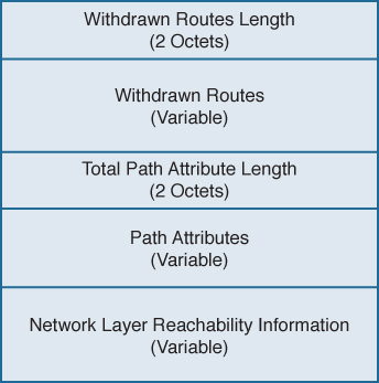
Figure 2-20 BGP Update Message Format
The BGP Update message contains the following fields:
Withdrawn Routes Length6: A 2-octet field indicating the total length of the following Withdrawn Routes field, in octets. A value of zero indicates that no routes are being withdrawn and that no Withdrawn Routes field is included in the message.
Withdrawn Routes: A variable-length field containing a list of routes to be withdrawn from service. Each route in the list is described with a (Length, Prefix) tuple in which the Length is the length of the prefix and the Prefix is the IP address prefix of the withdrawn route. If the Length part of the tuple is zero, the Prefix matches all routes.
Total Path Attribute Length: A 2-octet field indicating the total length of the following Path Attribute field, in octets. A value of zero indicates that attributes and NLRI are not included in this message.
Path Attributes: A variable-length field listing the attributes associated with the NLRI in the following field. Each path attribute is a variable-length triple of (Attribute Type, Attribute Length, Attribute Value). The Attribute Type part of the triple is a 2octet field consisting of four flag bits, four unused bits, and an Attribute Type code (see Figure 2-21). Table 2-4 shows the most common Attribute Type codes and the possible Attribute Values for each Attribute Type.
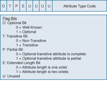
Figure 2-21 Attribute Type Part of the Path Attributes Field in the Update Message
Network Layer Reachability Information: A variable-length field containing a list of (Length, Prefix) tuples. The Length indicates the length in bits of the following prefix, and the Prefix is the IP address prefix of the NLRI. A Length value of zero indicates a prefix that matches all IP addresses.
)
Table 2-4 Attribute Types and Associated Attribute Values7
Attribute Type Code |
Attribute Type |
Attribute Value Code |
Attribute Value |
1 |
ORIGIN |
0 |
IGP |
|
|
1 |
EGP |
|
|
2 |
Incomplete |
2 |
AS_PATH |
1 |
AS_SET |
|
|
2 |
AS_SEQUENCE |
|
|
3 |
AS_CONFED_SET |
|
|
4 |
AS_CONFED_ SEQUENCE |
3 |
NEXT_HOP |
0 |
Next-hop IP address |
4 |
MULTI_EXIT_DISC |
0 |
4-octet MED |
5 |
LOCAL_PREF |
0 |
4-octet LOCAL_PREF |
6 |
ATOMIC_AGGREGATE |
0 |
None |
7 |
AGGREGATOR |
0 |
AS number and IP address of aggregator |
8 |
COMMUNITY |
0 |
4-octet community identifier |
9 |
ORIGINATOR_ID |
0 |
4-octet router ID of originator |
10 |
CLUSTER_LIST |
0 |
Variable-length list of cluster IDs |
14 |
MP_REACH_NLRI |
0 |
Variable-length Multiprotocol BGP NLRI |
15 |
MP_UNREACH_NLRI |
0 |
Variable-length Multiprotocol BGP NLRI |
16 |
EXTENDED COMMUNITIES |
0 |
16-octet extended community identifier |
17 |
AS4_PATH |
0 |
AS path with 4-octet AS numbers |
18 |
AS4_AGGREGATOR |
0 |
4-octet AS number and IP address of aggregator |
Keepalive Message
Keepalive messages are exchanged on a period one-third the hold time but not less than 1 second. If the negotiated hold time is 0, Keepalives are not sent.
The Keepalive message consists of only the 19-octet BGP message header, with no additional data.
Notification Message
Notification messages, whose format is shown in Figure 2-22, are sent when an error condition is detected. The BGP connection is closed immediately after the message is sent.
)
Figure 2-22 BGP Notification Message Format
The BGP Notification message contains the following fields:
Error Code: A 1-octet field indicating the type of error.
Error Subcode: A 1-octet field providing more-specific information about the error. Table 2-5 shows the possible error codes and associated error subcodes.
Data: A variable-length field used to diagnose the reason for the error. The contents of the Data field depend on the error code and subcode.
Table 2-5 BGP Notification Message Error Codes and Error Subcodes
Error Code |
Error |
Error Subcode |
Subcode Detail |
1 |
Message Header Error |
1 |
Connection not synchronized |
|
|
2 |
Bad message length |
|
|
3 |
Bad message type |
2 |
Open Message Error |
1 |
Unsupported version number |
|
|
2 |
Bad peer AS |
|
|
3 |
Bad BGP identifier |
|
|
4 |
Unsupported optional parameter |
|
|
5 |
Authentication failure (deprecated in RFC 4271) |
|
|
6 |
Unacceptable hold time |
3 |
Update Message Error |
1 |
Malformed attribute list |
|
|
2 |
Unrecognized well-known attribute |
|
|
3 |
Missing well-known attribute |
|
|
4 |
Attribute flags error |
|
|
5 |
Attribute length error |
|
|
6 |
Invalid ORIGIN attribute |
|
|
7 |
AS routing loop (deprecated in RFC 4271) |
|
|
8 |
Invalid NEXT_HOP attribute |
|
|
9 |
Optional attribute error |
|
|
10 |
Invalid network field |
|
|
11 |
Malformed AS_PATH |
4 |
Hold Timer Expired |
0 |
— |
5 |
Finite State Machine Error |
0 |
— |
6 |
Cease |
0 |
— |
Configuring and Troubleshooting BGP Peering
Many newcomers to BGP approach the protocol with trepidation. The source of this sentiment is that BGP implementations are rarer than IGP implementations. Outside of ISPs, most network administrators deal with BGP far less than with IGPs, if at all. And even when BGP is used, the configurations in small ISPs and non-ISP subscribers are usually quite basic. Because most networking professionals lack in-depth experience with the protocol, it is often viewed as intimidating.
BGP configurations can unarguably be complex. But most of the complexity around BGP involves policy. BGP peering configuration, although still a little more involved than most IGP configurations, is not at all difficult. This section takes you step-by-step through the configuration of BGP peering, from the most basic elements to more refined setups.
Case Study: EBGP Peering
A BGP session between routers is configured in two steps:
Step 1. Establish the BGP process and specify the local AS number with router bgp.
Step 2. Specify a neighbor and the neighbor’s AS number with neighbor remote-as.
Figure 2-23 shows two routers in different autonomous systems, and Example 2-6 shows their EBGP configurations.
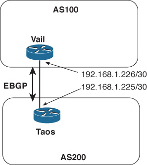
Figure 2-23 An EBGP Session Is Established Between Taos and Vail
Example 2-6 EBGP Configurations for the Routers in Figure 2-23
Taos
router bgp 200
 neighbor 192.168.1.226 remote-as 100
Vail
router bgp 100
 neighbor 192.168.1.225 remote-as 200
The BGP state changes at Vail can be seen, in Example 2-7, using debug ip bgp.8 In the first few lines, Vail is attempting to open a connection to Taos (192.168.1.225); BGP is not yet enabled at Taos, so the attempts fail and Vail shows Taos in Active state. Then as BGP comes up at Taos, a TCP connection is accepted; its state transitions from Active to OpenSent as Vail sends an Open message to begin the BGP session. The two routers then negotiate capabilities. (The multiprotocol and route refresh capabilities negotiated in this example are discussed in Chapters 6 and 4, respectively.) With capabilities agreed upon, Vail changes Taos’ state from OpenSent to OpenConfirm and then to Established.
Example 2-7 debug Is Used to Observe Vail’s BGP State Changes for Taos as the BGP Session Comes Up
Vail#debug ip bgp
BGP debugging is on for address family: IPv4 Unicast
Vail#
BGP: 192.168.1.225 open active, local address 192.168.1.226
BGP: 192.168.1.225 open failed: Connection refused by remote host, open active d
elayed 34034ms (35000ms max, 28% jitter)
BGP: 192.168.1.225 open active, local address 192.168.1.226
BGP: 192.168.1.225 went from Active to OpenSent
BGP: 192.168.1.225 sending OPEN, version 4, my as: 100, holdtime 180 seconds
BGP: 192.168.1.225 send message type 1, length (incl. header) 45
BGP: 192.168.1.225 rcv message type 1, length (excl. header) 26
BGP: 192.168.1.225 rcv OPEN, version 4, holdtime 180 seconds
BGP: 192.168.1.225 rcv OPEN w/ OPTION parameter len: 16
BGP: 192.168.1.225 rcvd OPEN w/ optional parameter type 2 (Capability) len 6
BGP: 192.168.1.225 OPEN has CAPABILITY code: 1, length 4
BGP: 192.168.1.225 OPEN has MP_EXT CAP for afi/safi: 1/1
BGP: 192.168.1.225 rcvd OPEN w/ optional parameter type 2 (Capability) len 2
BGP: 192.168.1.225 OPEN has CAPABILITY code: 128, length 0
BGP: 192.168.1.225 OPEN has ROUTE-REFRESH capability(old) for all address-families
BGP: 192.168.1.225 rcvd OPEN w/ optional parameter type 2 (Capability) len 2
BGP: 192.168.1.225 OPEN has CAPABILITY code: 2, length 0
BGP: 192.168.1.225 OPEN has ROUTE-REFRESH capability(new) for all address-families
BGP: 192.168.1.225 rcvd OPEN w/ remote AS 200
BGP: 192.168.1.225 went from OpenSent to OpenConfirm
BGP: 192.168.1.225 went from OpenConfirm to Established
When you create a neighbor with the neighbor remote-as statement, an entry is created in the BGP neighbor database for the specified neighbor. The command show ip bgp neighbor9 displays either the entire BGP neighbor database or a specified neighbor entry. In Example 2-8, the information Vail has recorded about Taos displays. The information in this display is particularly useful for troubleshooting.
The first line of output in Example 2-8 shows the address of Taos (192.168.1.225), its AS number (200), and the type of BGP connection to the router (external). The second line displays the BGP version used between Vail and Taos, and Taos’ router ID. The third line begins by showing the state of the BGP finite state machine and then the time since the present peer connection was established. In this example, Taos has been peered continuously for 23 minutes and 25 seconds.
Also of interest are the details of the underlying TCP connection, the second set of highlighted lines in Example 2-8. They show that the TCP connection state is Established, that Vail is originating BGP messages from TCP port 13828, and that the destination port at Taos is 179. The source port can be especially important to note when you capture packets on a link carrying more than one BGP session.
Example 2-8 show ip bgp neighbors Command Output Contains Essential Details About the Peer Connection to a Neighbor
Vail#show ip bgp neighbors

BGP neighbor is 192.168.1.225,  remote AS 200, external link
  BGP version 4, remote router ID 192.168.1.225
  BGP state = Established, up for 00:23:25
  Last read 00:00:25, last write 00:00:25, hold time is 180, keepalive interval
is 60 seconds
  Neighbor capabilities:
    Route refresh: advertised and received(old & new)
    Address family IPv4 Unicast: advertised and received
  Message statistics:
    InQ depth is 0
    OutQ depth is 0
                         Sent       Rcvd
    Opens:                  5          5
    Notifications:          0          0
    Updates:                0          0
    Keepalives:            51         52
    Route Refresh:          0          0
    Total:                 56         57
  Default minimum time between advertisement runs is 30 seconds

 For address family: IPv4 Unicast
  BGP table version 1, neighbor version 1/0
  Output queue size: 0
  Index 1, Offset 0, Mask 0x2
  1 update-group member
                                 Sent       Rcvd
  Prefix activity:               ----       ----
    Prefixes Current:               0          0
    Prefixes Total:                 0          0
    Implicit Withdraw:              0          0
    Explicit Withdraw:              0          0
    Used as bestpath:             n/a          0
    Used as multipath:            n/a          0

                                   Outbound    Inbound
  Local Policy Denied Prefixes:    --------    -------
    Total:                                0          0
  Number of NLRIs in the update sent: max 0, min 0

  Connections established 5; dropped 4
  Last reset 00:26:11, due to Peer closed the session
Connection state is ESTAB, I/O status: 1, unread input bytes: 0
Connection is ECN Disabled, Mininum incoming TTL 0, Outgoing TTL 1
Local host: 192.168.1.226, Local port: 13828
Foreign host: 192.168.1.225, Foreign port: 179
Connection tableid (VRF): 0

Enqueued packets for retransmit: 0, input: 0  mis-ordered: 0 (0 bytes)

Event Timers (current time is 0xA9F664):
Timer          Starts    Wakeups            Next
Retrans            26          0             0x0
TimeWait            0          0             0x0
AckHold            25          2             0x0
SendWnd             0          0             0x0
KeepAlive           0          0             0x0
GiveUp              0          0             0x0
PmtuAger            0          0             0x0
DeadWait            0          0             0x0
Linger              0          0             0x0
ProcessQ            0          0             0x0

iss:  842497347  snduna:  842497887  sndnxt:  842497887     sndwnd:  15845
irs: 2329656545  rcvnxt: 2329657085  rcvwnd:      15845  delrcvwnd:    539

SRTT: 435 ms, RTTO: 1159 ms, RTV: 724 ms, KRTT: 0 ms
minRTT: 212 ms, maxRTT: 992 ms, ACK hold: 200 ms
Status Flags: active open
Option Flags: nagle
IP Precedence value : 6

Datagrams (max data segment is 1460 bytes):
Rcvd: 50 (out of order: 0), with data: 25, total data bytes: 539
Sent: 31 (retransmit: 0, fastretransmit: 0, partialack: 0, Second Congestion: 0)
, with data: 26, total data bytes: 539
 Packets received in fast path: 0, fast processed: 0, slow path: 0
 fast lock acquisition failures: 0, slow path: 0
Vail#
Case Study: EBGP Peering over IPv6
The TCP connection between BGP routers can run over either IPv4 or IPv6. Keep in mind that the endpoint addresses of the TCP session have nothing to do with the address families supported by the BGP session running over the TCP connection or the types of prefixes exchanged by BGP. BGP peers can exchange both IPv4 and IPv6 prefixes regardless of whether the TCP session is between IPv4 addresses or IPv6 addresses.
Figure 2-24 shows the same two routers of Figure 2-23, except that in this case, the interfaces have IPv6 addresses. Example 2-9 shows the EBGP configurations for these two routers, and you can readily see that they are the same as the configurations in the previous case study except that the neighbor addresses are IPv6.
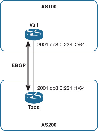
Figure 2-24 An EBGP Session Is Established Between Taos and Vail, This Time with IPv6 Endpoints
Example 2-9 EBGP Configurations for the Routers in Figure 2-24
Taos
router bgp 200
 neighbor 2001:db8:0:224::1 remote-as 100
Vail
router bgp 100
 neighbor 2001:db8:0:224::2 remote-as 200
Example 2-10 shows another output from show ip bgp neighbors at Vail, after the configurations of Example 2-9 have been implemented. The neighbor information looks almost identical to that of Example 2-8 (the same fields are highlighted) except the addresses are now IPv6 addresses. Notice, however, that Vail’s BGP router ID remains 192.168.1.225; the BGP router ID is a 32-bit number so cannot be taken from an IPv6 address.
Example 2-10 The Neighbor Database Looks Almost Identical to the One in Example 2-8, Except the Neighbor Addresses Are IPv6
Vail#show ip bgp neighbors

BGP neighbor is 2001:DB8:0:224::1,  remote AS 200, external link
  BGP version 4, remote router ID 192.168.1.225
  BGP state = Established, up for 00:00:18
  Last read 00:00:18, last write 00:00:18, hold time is 180, keepalive interval
is 60 seconds
  Neighbor capabilities:
    Route refresh: advertised and received(old & new)
    Address family IPv4 Unicast: advertised and received
  Message statistics:
    InQ depth is 0
    OutQ depth is 0
                         Sent       Rcvd
    Opens:                  6          6
    Notifications:          0          0
    Updates:                0          0
    Keepalives:           240        280
    Route Refresh:          0          0
    Total:                246        286
  Default minimum time between advertisement runs is 30 seconds

 For address family: IPv4 Unicast
  BGP table version 1, neighbor version 1/0
  Output queue size: 0
  Index 1, Offset 0, Mask 0x2
  1 update-group member
                                 Sent       Rcvd
  Prefix activity:               ----       ----
    Prefixes Current:               0          0
    Prefixes Total:                 0          0
    Implicit Withdraw:              0          0
    Explicit Withdraw:              0          0
    Used as bestpath:             n/a          0
    Used as multipath:            n/a          0

                                   Outbound    Inbound
  Local Policy Denied Prefixes:    --------    -------
    Total:                                0          0
  Number of NLRIs in the update sent: max 0, min 0
  Connections established 6; dropped 5
  Last reset 00:00:39, due to Peer closed the session
Connection state is ESTAB, I/O status: 1, unread input bytes: 0
Connection is ECN Disabled, Mininum incoming TTL 0, Outgoing TTL 1
Local host: 2001:DB8:0:224::2, Local port: 179
Foreign host: 2001:DB8:0:224::1, Foreign port: 59051
Connection tableid (VRF): 0

Enqueued packets for retransmit: 0, input: 0  mis-ordered: 0 (0 bytes)

Event Timers (current time is 0x285A1B0):
Timer          Starts    Wakeups            Next
Retrans             3          0             0x0
TimeWait            0          0             0x0
AckHold             2          0             0x0
SendWnd             0          0             0x0
KeepAlive           0          0             0x0
GiveUp              0          0             0x0
PmtuAger            0          0             0x0
DeadWait            0          0             0x0
Linger              0          0             0x0
ProcessQ            0          0             0x0

iss: 1579724289  snduna: 1579724392  sndnxt: 1579724392     sndwnd:  16282
irs: 4090406841  rcvnxt: 4090406944  rcvwnd:      16282  delrcvwnd:    102

SRTT: 253 ms, RTTO: 2915 ms, RTV: 2662 ms, KRTT: 0 ms
minRTT: 40 ms, maxRTT: 1484 ms, ACK hold: 200 ms
Status Flags: passive open, gen tcbs
Option Flags: nagle
IP Precedence value : 6

Datagrams (max data segment is 1440 bytes):
Rcvd: 6 (out of order: 0), with data: 3, total data bytes: 102
Sent: 3 (retransmit: 0, fastretransmit: 0, partialack: 0, Second Congestion: 0),
 with data: 3, total data bytes: 230
 Packets received in fast path: 0, fast processed: 0, slow path: 0
 fast lock acquisition failures: 0, slow path: 0
Also highlighted in this neighbor data are the fields showing that the session supports only IPv4 unicast prefix advertisements; the routers’ BGP sessions have not been configured to carry any other address families (as demonstrated in Chapter 6). So this EBGP session, although running between IPv6 endpoints, can carry only IPv4 prefixes—the default address family.
There is one small difference between the TCP sessions in Examples 2-8 and 2-10; it has nothing to do with IPv4 or IPv6 but is nevertheless worth noting. In Example 2-8, the local (Vail’s) TCP port is ephemeral whereas the remote (Taos’) TCP port is 179. Example 2-10 is just the opposite: Vail’s local TCP port is 179 and the remote TCP port at Taos is ephemeral. What this indicates is that in the first case, Vail initiated the TCP connection (the TCP initiation is always directed at port 179 for BGP), whereas in the second case Taos initiated the TCP connection. This is consistent with the historical facts of the connections: In configuring the first example, Vail’s BGP was configured before Taos (and you can observe in Example 2-7 Vail trying to connect to Taos before Taos is ready); in the second example, Taos’ BGP was configured before Vail. Noticing small details such as this one can be useful when you troubleshoot or just try to fully understand a particular BGP session. Such details can also be important if you run an access list on a BGP interface. The ACL might be configured to permit TCP port 179, but depending on the direction of the session might inadvertently block the ephemeral port.
Case Study: IBGP Peering
Figure 2-25 shows another AS, AS400, connected to AS100. (The interfaces connecting Vail and Taos are again IPv4, for simplicity’s sake.) Two more routers, Aspen and Telluride, are added within AS100 and Telluride connects to Alta, in AS400, via EBGP.
)
Figure 2-25 Two Routers Are Added to AS100 and Are Peering via IBGP So That AS200 and AS400 Can Communicate Across AS100
Each of the three routers in AS100 has an IBGP peering session with the other two routers in the same AS. Recall from the section “External and Internal BGP” in Chapter 1 that a full IBGP mesh—a direct IBGP connection between every BGP router within the same AS—is required for two reasons:
The AS_PATH attribute is meaningless within a single AS, so IBGP has no loop avoidance mechanism. A full IBGP mesh means every BGP router directly advertises its prefixes to every other BGP router in the same AS, removing any need for a router to advertise prefixes learned from one internal peer to another internal peer, which could lead to routing loops. A default BGP rule reinforces the full mesh requirement: BGP cannot advertise routes learned from an internal neighbor to another internal neighbor.10
Every BGP router along a forwarding path must know the BGP routes used at the routers with external peers so that packets forwarded to a purely internal BGP router on their way to an external next hop are not dropped by the internal router. For instance, in Figure 2-25 a packet traveling from AS400 to AS200 would be received by Telluride; Telluride’s BGP route to the AS200 destination would have a next-hop address of 192.168.1.225 (Taos’ external interface). Telluride would forward the packet to Aspen to get to that next hop, assuming Vail is advertising the subnet internally. But if Aspen does not also know the BGP route to the AS200 destination, it drops the packet. Therefore, in addition to the IBGP session between Vail and Telluride, each of those externally connected routers must tell Aspen about its external routes.
At a basic level, IBGP peering is configured exactly the same as EBGP peering; it is IBGP rather than EBGP only in that the AS number referenced by neighbor remote-as is the same as the local AS number referenced by router bgp. Example 2-11 shows the configurations for Vail, Aspen, and Telluride. The router bgp statements in all three configurations show that the routers are all in AS100; you can then easily see what neighbor remote-as statements in each configuration point to AS100, and from that you know that those sessions are IBGP.
Example 2-11 Configurations for the Routers of AS100 in Figure 2-25
Vail
router bgp 100
 neighbor 192.168.1.197 remote-as 100
 neighbor 192.168.1.222 remote-as 100
 neighbor 192.168.1.225 remote-as 200
Aspen
router bgp 100
 neighbor 192.168.1.197 remote-as 100
 neighbor 192.168.1.221 remote-as 100
Telluride
router bgp 100
 neighbor 192.168.1.198 remote-as 100
 neighbor 192.168.1.205 remote-as 400
 neighbor 192.168.1.221 remote-as 100
Example 2-12 introduces another command you can use regularly when maintaining and troubleshooting BGP networks: show ip bgp summary.11 This command gives you an overview of the BGP peerings configured on the router and the state of each of those peerings. The output from this command first shows you the local router’s BGP router ID and AS number, and the current version of the BGP table. (The table version is incremented when policies or other activities change the contents of the table.) After this information a table lists the following for each configured neighbor:
The address configured in the neighbor remote-as statement
The BGP version used for that neighbor
The neighbor’s AS number
The number of BGP messages received from and sent to the neighbor
The last version of the local BGP table sent to the neighbor
The number of messages in queue from and to the neighbor
The length of time the BGP session has been Established with the neighbor, or the status of the neighbor if not in Established state
The state of the neighbor if not Established; or if the state is Established, the number of prefixes received from the neighbor
Example 2-12 Although the Other BGP Sessions Are Established, the IBGP Peering Between Vail and Telluride Is Not; Its State Is Active
! Vail
Vail#show ip bgp summary

BGP router identifier 192.168.1.226, local AS number 100
BGP table version is 1, main routing table version 1

Neighbor        V    AS MsgRcvd MsgSent   TblVer  InQ OutQ Up/Down  State/PfxRcd
192.168.1.197   4   100       0       0        0    0    0 never    Active
192.168.1.222   4   100      29      22        1    0    0 00:18:59        0
192.168.1.225   4   200      43      43        1    0    0 00:00:12        0
! Aspen
Aspen#show ip bgp summary
BGP router identifier 192.168.1.222, local AS number 100
BGP table version is 1, main routing table version 1
Neighbor        V    AS MsgRcvd MsgSent   TblVer  InQ OutQ Up/Down  State/PfxRcd
192.168.1.197   4   100      12      20        1    0    0 00:15:43        0
192.168.1.221   4   100      23      30        1    0    0 00:26:14        0
! Telluride
Telluride#show ip bgp summary
BGP router identifier 192.168.1.206, local AS number 100
BGP table version is 1, main routing table version 1

Neighbor        V    AS MsgRcvd MsgSent   TblVer  InQ OutQ Up/Down  State/PfxRcd
192.168.1.198   4   100      21      13        1    0    0 00:10:06        0
192.168.1.205   4   400       4       5        1    0    0 00:01:06        0
192.168.1.221   4   100       0       0        0    0    0 never    Active
The three displays in Example 2-12 show that all the EBGP and IBGP sessions are Established except for the IBGP session between Vail (192.168.1.221) and Telluride (192.168.1.197); Vail and Telluride each show the other in Active state. A quick look at Vail’s routing table (Example 2-13) reveals the problem: Vail has no route to Telluride’s interface 192.168.1.197. Although its routing table is not shown here, Telluride does not have a route to Vail’s interface 192.168.1.221 either.
Example 2-13 Vail Does Not Have a Route to 192.168.1.197 and Cannot Establish an IBGP Session with Telluride
Vail#show ip route

Codes: C - connected, S - static, R - RIP, M - mobile, B - BGP
       D - EIGRP, EX - EIGRP external, O - OSPF, IA - OSPF inter area
       N1 - OSPF NSSA external type 1, N2 - OSPF NSSA external type 2
       E1 - OSPF external type 1, E2 - OSPF external type 2
       i - IS-IS, su - IS-IS summary, L1 - IS-IS level-1, L2 - IS-IS level-2
       ia - IS-IS inter area, * - candidate default, U - per-user static route
       o - ODR, P - periodic downloaded static route

Gateway of last resort is not set

     192.168.1.0/30 is subnetted, 2 subnets
C       192.168.1.224 is directly connected, Serial1/0
C       192.168.1.220 is directly connected, FastEthernet0/0
Vail#
This simple example demonstrates a problem commonly encountered when working with IBGP. Unlike IGPs, IBGP sessions often span multiple router hops; a router cannot establish an IBGP session unless it knows how to reach its peer. Therefore, one of the first steps in troubleshooting an IBGP session that stays in Active state (listening for a configured neighbor) is to look in the routing tables of both neighbors and see if they know how to find each other.
The problem with the IBGP session between Vail and Telluride is resolved by configuring an IGP within AS100—in this example, OSPF is used, but anything that gives the neighbors the reachability information they need in their routing tables can work. Example 2-14 shows that Vail’s routing table now has a route to subnet 192.168.1.196 and to the neighbor address 192.168.1.197 configured for Telluride. Example 2-15 shows that with the three routers in AS100 now exchanging internal reachability information via OSPF, all IBGP sessions are Established.
Example 2-14 After an IGP (OSPF in This Case) Is Configured, Vail Has a Route to Telluride
Vail#show ip route

Codes: C - connected, S - static, R - RIP, M - mobile, B - BGP
       D - EIGRP, EX - EIGRP external, O - OSPF, IA - OSPF inter area
       N1 - OSPF NSSA external type 1, N2 - OSPF NSSA external type 2
       E1 - OSPF external type 1, E2 - OSPF external type 2
       i - IS-IS, su - IS-IS summary, L1 - IS-IS level-1, L2 - IS-IS level-2
       ia - IS-IS inter area, * - candidate default, U - per-user static route
       o - ODR, P - periodic downloaded static route

Gateway of last resort is not set


     192.168.1.0/30 is subnetted, 3 subnets
C       192.168.1.224 is directly connected, Serial1/0
O       192.168.1.196 [110/2] via 192.168.1.222, 00:00:07, FastEthernet0/0
C       192.168.1.220 is directly connected, FastEthernet0/0
Vail#
Example 2-15 Vail and Telluride Now Know How to Find Each Other and Their IBGP Session Is Established
Vail#show ip bgp summary
BGP router identifier 192.168.1.226, local AS number 100


BGP table version is 1, main routing table version 1

Neighbor        V    AS MsgRcvd MsgSent   TblVer  InQ OutQ Up/Down  State/PfxRcd
192.168.1.197   4   100       4       4        1    0    0 00:00:05        0
192.168.1.222   4   100      93      56        1    0    0 00:00:56        0
192.168.1.225   4   200     131     142        1    0    0 00:00:05        0
Aspen#show ip bgp summary
BGP router identifier 192.168.1.222, local AS number 100


BGP table version is 1, main routing table version 1

Neighbor        V    AS MsgRcvd MsgSent   TblVer  InQ OutQ Up/Down  State/PfxRcd
192.168.1.197   4   100      47      81        1    0    0 00:02:53        0
192.168.1.221   4   100      57      95        1    0    0 00:03:31        0
Telluride#show ip bgp summary
BGP router identifier 192.168.1.206, local AS number 100
BGP table version is 1, main routing table version 1

Neighbor        V    AS MsgRcvd MsgSent   TblVer  InQ OutQ Up/Down  State/PfxRcd
192.168.1.198   4   100      82      47        1    0    0 00:02:09        0
192.168.1.205   4   400      84      73        1    0    0 00:01:03        0
192.168.1.221   4   100       5       5        1    0    0 00:01:37        0
The IBGP configurations are now sufficient for the topology in Figure 2-25; however, the topology has a problem: If the link between Telluride and Aspen or the link between Aspen and Vail fails, AS100 and AS400 can no longer communicate. AS100 needs a more resilient topology both for packet forwarding and for BGP information exchange. A link added between Telluride and Vail, as shown in Figure 2-26, gives AS100 the redundancy to survive the failure of a single internal link.
)
Figure 2-26 A Link Between Vail and Telluride Gives AS100 Some Redundancy
Although the added link does provide some redundancy, it raises a question about the IBGP configuration for AS100. If a link fails, you want the IBGP sessions that were using the link to be rerouted across the alternative path. With the IBGP sessions running between physical interfaces, you cannot be sure that this will happen. One remedy might be to configure redundant IBGP sessions. For example, Vail and Telluride might be configured for peering both between 192.168.1.193 and 192.168.1.194 and between 192.168.1.221 and 192.168.1.197. However, as the topology of an AS grows in complexity, this approach (configuring all routers with redundant IBGP connections to all physical interfaces) quickly escalates to undesirably long BGP configurations and to an undesirable number of IBGP sessions.
A better approach is to peer not between physical interfaces but between loopback interfaces, as shown in Figure 2-27. Note that the physical links have been removed from the drawing; when you peer between loopback addresses, you remove physical interface dependencies from the IBGP topology. Only a single IBGP session between each router within the AS is required, and that session is routed over the best available path. Should a link on that path fail, the session is rerouted—in most cases rerouted fast enough that the BGP session does not fail—over the next best path.
)
Figure 2-27 Using Loopback Interfaces as the IBGP Endpoints Eliminates Any Dependencies on Physical Interfaces
Configuring IBGP peering between loopback interfaces requires an extra configuration statement. You not only specify the neighbor’s loopback address instead of a physical address for the remote end of the session, you must also specify the local router’s loopback interface as the originating end of the session.
Example 2-16 shows an improved configuration for Vail. The EBGP configuration remains the same, but the neighbor remote-as statements for Aspen and Telluride now point to those routers’ loopback interface addresses rather than physical interfaces as in the previous configuration examples. The IBGP configurations of Aspen and Telluride also now point to loopback interfaces instead of physical interfaces.
But that is not enough. By default, an outgoing TCP session is sourced from its outgoing physical interface address. If every router in Figure 2-27 tried to originate its IBGP TCP session from a physical interface and going to a loopback interface, although its peer also originates at a physical interface and terminates at the local router’s loopback, the endpoints of the attempted TCP sessions never match and the sessions do not come up.
So neighbor update-source tells the router to originate the TCP session going to the specified neighbor from the specified local loopback interface.
Example 2-16 Peering Between Loopback Addresses Requires the neighbor update-source Statement to Indicate That the Local End of the Session Should Be Sourced from the Local Loopback Interface, as Shown in Vail’s Modified Configuration
router bgp 100

 neighbor 192.168.1.225 remote-as 200
 neighbor 192.168.100.2 remote-as 100
 neighbor 192.168.100.2 update-source Loopback0
 neighbor 192.168.100.3 remote-as 100
 neighbor 192.168.100.3 update-source Loopback0
Example 2-17 shows the results of the three routers of AS100 in Figure 2-27. The IBGP sessions are all up (because of OSPF advertising the loopback addresses). You can also observe another difference from the earlier observed sessions. Recall from the discussion in the section on the Open message than BGP chooses its router ID the same way OSPF does: It prefers the loopback address and chooses the numerically highest physical interface address if the loopback is not available. With the new configuration we have made loopback addresses available, and you can see that the BGP router IDs in each of Example 2-17’s three displays are the loopback address of that router. Because the same loopback address is probably used to identify the router in several other ways, such as the OSPF router ID and even as a DNS entry for telnetting to the router by name, using the loopback for the BGP router ID enforces consistency and makes the BGP ID easily recognizable.
The Case Study “Managing and Securing BGP Sessions” shows you an even better way to configure a predictable and consistent BGP router ID.
Example 2-17 The IBGP Sessions Now Run Between Loopback Interfaces Instead of Physical Interfaces
Vail#show ip bgp summary
BGP router identifier 192.168.100.1, local AS number 100
BGP table version is 1, main routing table version 1

Neighbor        V    AS MsgRcvd MsgSent   TblVer  InQ OutQ Up/Down  State/PfxRcd
192.168.1.225   4   200       5       5        1    0    0 00:01:09        0
192.168.100.2   4   100      15      14        1    0    0 00:11:26        0
192.168.100.3   4   100      12      13        1    0    0 00:09:00        0
Aspen#show ip bgp summary
BGP router identifier 192.168.100.2, local AS number 100
BGP table version is 1, main routing table version 1

Neighbor        V    AS MsgRcvd MsgSent   TblVer  InQ OutQ Up/Down  State/PfxRcd
192.168.100.1   4   100      14      14        1    0    0 00:11:42        0
192.168.100.3   4   100      11      13        1    0    0 00:08:59        0
Telluride#show ip bgp summary
BGP router identifier 192.168.100.3, local AS number 100
BGP table version is 1, main routing table version 1

Neighbor        V    AS MsgRcvd MsgSent   TblVer  InQ OutQ Up/Down  State/PfxRcd
192.168.1.205   4   400       8       7        1    0    0 00:03:02        0
192.168.100.1   4   100      20      20        1    0    0 00:17:09        0
192.168.100.2   4   100      21      19        1    0    0 00:16:51        0
Case Study: Connected Check and EBGP Multihop
Only the IBGP sessions in the previous example run between loopback addresses. The EBGP sessions still run between directly connected physical interfaces, and that is standard practice for the great majority of EBGP sessions. The IOS default settings ensure that external BGP peers are directly connected by two means:
Setting a TTL value of 1 in packets containing BGP messages to external neighbors so that if the packet crosses a router hop the TTL is decremented to 0 and the packet is dropped
Checking the IP address of the configured neighbor to ensure that it belongs to a directly connected subnet
However, there are cases in which running EBGP between loopback interfaces is useful. Consider Figure 2-28, in which Telluride and Alta are connected by four equal-cost links. Configuring four separate EBGP sessions, one for each link, is undesirable because you do not want the added configuration complexity. More important, such a configuration causes BGP to advertise four identical sets of prefixes between the routers, reducing network scalability.
)
Figure 2-28 Four Equal-Cost Links Connect Telluride and Alta
At the same time, you do not want to choose just one of the four links to carry the EBGP session. If that link was to fail, EBGP would fail even though there are still three good links between the routers. You want to take advantage of the redundancy and load-sharing capabilities of the four parallel links. A solution for this case12 is to run EBGP between the routers’ loopback interfaces, as shown in Figure 2-29.
)
Figure 2-29 Using Loopback Interfaces for the EBGP Endpoints Takes Advantage of the Redundancy and Load Sharing of Multiple Physical Links
The configuration is similar to the configurations in the preceding IBGP example: You specify the neighbor’s loopback address as the neighbor address, use the neighbor update-source statement to source the session from the local loopback interface, and give the routers on each side a means of finding the remote peering address. By definition an IGP is not run between routers in different autonomous systems, so in this case, static routes are used; for each physical link, a static route is configured pointing to the remote loopback address and specifying the address of the far end of the link as the next hop. Example 2-18 shows Alta’s EBGP configuration; Telluride’s configuration is similar.
Example 2-18 Alta’s EBGP Configuration Specifies That EBGP Messages It Originates to Neighbor 192.168.100.3 (Telluride) Are Originated from Its Loopback0 Interface, and Static Routes Are Configured to Find the Neighbor Address Across All Four of the Physical Links
router bgp 400
 no synchronization
 bgp log-neighbor-changes
 neighbor 192.168.100.3 remote-as 100
 neighbor 192.168.100.3 disable-connected-check
 neighbor 192.168.100.3 update-source Loopback0
 no auto-summary
!
ip route 192.168.100.3 255.255.255.255 192.168.1.206
ip route 192.168.100.3 255.255.255.255 192.168.1.210
ip route 192.168.100.3 255.255.255.255 192.168.1.214
ip route 192.168.100.3 255.255.255.255 192.168.1.218
Example 2-19 shows that Alta’s neighbor state to Telluride is Idle. A closer look shows, near the bottom of the display, that there is no active TCP session because the neighbor address 192.168.100.3 is not directly connected. This is the connected check that IOS does by default for EBGP neighbors.
Example 2-19 The Neighbor State to Telluride Is Idle Because the IOS Default Connected Check Shows That the Address Is Not Directly Connected to a Local Subnet
Alta#show ip bgp neighbor 192.168.100.3
BGP neighbor is 192.168.100.3,  remote AS 100, external link
  BGP version 4, remote router ID 0.0.0.0
  BGP state = Idle
  Last read 00:00:00, last write 00:00:00, hold time is 180, keepalive interval is
  60 seconds
  Message statistics:
    InQ depth is 0
    OutQ depth is 0
                         Sent       Rcvd
    Opens:                  0          0
    Notifications:          0          0
    Updates:                0          0
    Keepalives:             0          0
    Route Refresh:          0          0
    Total:                  0          0
  Default minimum time between advertisement runs is 30 seconds

 For address family: IPv4 Unicast
  BGP table version 1, neighbor version 0/0
  Output queue size: 0
  Index 1, Offset 0, Mask 0x2
  1 update-group member
                                 Sent       Rcvd
  Prefix activity:               ----       ----
    Prefixes Current:               0          0
    Prefixes Total:                 0          0
    Implicit Withdraw:              0          0
    Explicit Withdraw:              0          0
    Used as bestpath:             n/a          0
    Used as multipath:            n/a          0

                                   Outbound    Inbound
  Local Policy Denied Prefixes:    --------    -------
    Total:                                0          0
  Number of NLRIs in the update sent: max 0, min 0

  Connections established 0; dropped 0
  Last reset never
  External BGP neighbor not directly connected.
  No active TCP connection
Alta#
For situations in which an external BGP neighbor is directly connected but the neighbor address is not a part of a local subnet—the most common instance of which is EBGP peering between loopback interfaces—you can disable the IOS connected check with the statement neighbor disable-connected-check. Example 2-20 shows Alta’s configuration with this statement added. The statement is also added to Telluride’s configuration. Example 2-21 shows that the BGP session between the two loopback addresses is now established.
Example 2-20 Alta’s EBGP Configuration Now Includes the neighbor disable-connected-check Statement
router bgp 400
 no synchronization
 bgp log-neighbor-changes
 neighbor 192.168.100.3 remote-as 100
 neighbor 192.168.100.3 disable-connected-check
 neighbor 192.168.100.3 update-source Loopback0
 no auto-summary
!
ip route 192.168.100.3 255.255.255.255 192.168.1.206
ip route 192.168.100.3 255.255.255.255 192.168.1.210
ip route 192.168.100.3 255.255.255.255 192.168.1.214
ip route 192.168.100.3 255.255.255.255 192.168.1.218
Example 2-21 With the Connected Check Disabled, the EBGP Session Between Alta and Telluride Is Now Established
Alta#show ip bgp neighbor 192.168.100.3
BGP neighbor is 192.168.100.3,  remote AS 100, external link
  BGP version 4, remote router ID 192.168.100.3
  BGP state = Established, up for 00:10:06
  Last read 00:00:05, last write 00:00:05, hold time is 180, keepalive interval is
  60 seconds
  Neighbor capabilities:

[Remaining output deleted]
Figure 2-30 depicts another EBGP peering scenario that is frequently encountered. An EBGP session is again running between the loopback interfaces of Alta and Telluride, but now the two routers are not directly connected. The session must pass through the router Copper, which is not running BGP at all. Copper might be a filtering router or some other security device that examines packets before they’re allowed to enter AS100, or it might be one of many edge routers that aggregate EBGP sessions to one or a few routers interior to AS100. The point is that just disabling the IOS connected check is not sufficient to make this scenario work because by default EBGP messages are sent with a TTL of 1. Packets passing from Alta to Copper to Telluride must have a TTL of at least 2 to account for the TTL being decremented by 1 as it passes through Copper.
)
Figure 2-30 EBGP Peering Scenario for Two Routers Not Directly Connected
aThe neighbor ebgp-multihop statement changes the default TTL in EBGP messages to specified neighbors. Example 2-22 shows the configurations of the three routers in Figure 2-30. Simple reachability is configured with OSPF between Telluride and Copper, a static route at Copper for Alta’s loopback address, and a static default route pointing to Copper at Alta. Most important, notice that there is no BGP running at Copper. The neighbor ebgp-multihop statement is used at Telluride and Alta to change the default TTL of their EBGP messages to 2; when the messages transit Copper the TTL is decremented to 1, and the messages safely arrive at their destination. If the messages had retained their default TTL of 1 upon transmission, the TTL would be decremented to 0 at Copper, and the packets would be dropped.
Example 2-22 Routers Telluride and Alta in Figure 2-30 Are Configured to Establish an EBGP Session Across Two Router Hops
Telluride
router ospf 1
 log-adjacency-changes
 network 0.0.0.0 255.255.255.255 area 0
!
router bgp 100
 no synchronization
 bgp log-neighbor-changes
 neighbor 192.168.200.1 remote-as 400
 neighbor 192.168.200.1 ebgp-multihop 2
 neighbor 192.168.200.1 update-source Loopback0
 no auto-summary
!
Copper
router ospf 1
 log-adjacency-changes
 redistribute static
 network 0.0.0.0 255.255.255.255 area 0
!
ip route 192.168.200.0 255.255.255.0 192.168.1.222
!
Alta
router bgp 400
 no synchronization
 bgp log-neighbor-changes
 neighbor 192.168.100.3 remote-as 100
 neighbor 192.168.100.3 ebgp-multihop 2
 neighbor 192.168.100.3 update-source Loopback0
 no auto-summary
!
ip route 0.0.0.0 0.0.0.0 192.168.1.221
Example 2-23 shows that Alta’s neighbor state for Telluride is Established. Looking further down the display, you can also see that the outgoing TTL is 2, changed from the default outgoing TTL of 1.
Example 2-23 Alta’s Neighbor State to Telluride (192.168.100.3) Is Established
Alta#show ip bgp neighbor 192.168.100.3
BGP neighbor is 192.168.100.3,  remote AS 100, external link
  BGP version 4, remote router ID 192.168.100.3
  BGP state = Established, up for 00:26:41
  Last read 00:00:41, last write 00:00:41, hold time is 180, keepalive interval is
  60 seconds
  Neighbor capabilities:
    Route refresh: advertised and received(old & new)
    Address family IPv4 Unicast: advertised and received
  Message statistics:
    InQ depth is 0
    OutQ depth is 0
                         Sent       Rcvd
    Opens:                  1          1
    Notifications:          0          0
    Updates:                0          0
    Keepalives:            28         28
    Route Refresh:          0          0
    Total:                 29         29
  Default minimum time between advertisement runs is 30 seconds

 For address family: IPv4 Unicast
  BGP table version 1, neighbor version 1/0
  Output queue size: 0
  Index 1, Offset 0, Mask 0x2
  1 update-group member
                                 Sent       Rcvd
  Prefix activity:               ----       ----
    Prefixes Current:               0          0
    Prefixes Total:                 0          0
    Implicit Withdraw:              0          0
    Explicit Withdraw:              0          0
    Used as bestpath:             n/a          0
    Used as multipath:            n/a          0

                                   Outbound    Inbound
  Local Policy Denied Prefixes:    --------    -------
    Total:                                0          0
  Number of NLRIs in the update sent: max 0, min 0

  Connections established 1; dropped 0
  Last reset never
  External BGP neighbor may be up to 2 hops away.
Connection state is ESTAB, I/O status: 1, unread input bytes: 0
Connection is ECN Disabled, Mininum incoming TTL 0, Outgoing TTL 2
Local host: 192.168.200.1, Local port: 179
Foreign host: 192.168.100.3, Foreign port: 29761
Connection tableid (VRF): 0

Enqueued packets for retransmit: 0, input: 0  mis-ordered: 0 (0 bytes)

Event Timers (current time is 0x22885C):
Timer          Starts    Wakeups            Next
Retrans            29          0             0x0
TimeWait            0          0             0x0
AckHold            29          1             0x0
SendWnd             0          0             0x0
KeepAlive           0          0             0x0
GiveUp              0          0             0x0
PmtuAger            0          0             0x0
DeadWait            0          0             0x0
Linger              0          0             0x0
ProcessQ            0          0             0x0

iss: 3118002936  snduna: 3118003514  sndnxt: 3118003514     sndwnd:  16346
irs: 3626178200  rcvnxt: 3626178778  rcvwnd:      16346  delrcvwnd:     38

SRTT: 294 ms, RTTO: 345 ms, RTV: 51 ms, KRTT: 0 ms
minRTT: 36 ms, maxRTT: 312 ms, ACK hold: 200 ms
Status Flags: passive open, gen tcbs
Option Flags: nagle
IP Precedence value : 6

Datagrams (max data segment is 536 bytes):
Rcvd: 58 (out of order: 0), with data: 29, total data bytes: 577
Sent: 31 (retransmit: 0, fastretransmit: 0, partialack: 0, Second Congestion: 0),
  with data: 28, total data bytes: 577
 Packets received in fast path: 0, fast processed: 0, slow path: 0
 fast lock acquisition failures: 0, slow path: 0
Alta#
You might ask why the neighbor disable-connected-check statement is not needed in this configuration. Alta and Telluride are obviously not directly connected, and the loopback addresses do not belong to the same subnet, yet just as obviously in Example 2-23 the EBGP session between their loopback interfaces works. The answer is that the connected check is automatically disabled when the neighbor ebgp-multihop statement increases the TTL
Using the neighbor ebgp multihop statement to change the TTL to 2 or more would make the scenario in Figure 2-29 work just as well as using the neighbor disable-connected-check statement did. This leads to a commonly held misconception that the TTL is decremented when a packet is sent to an IP address on a neighboring router when the destination address is not a part of a locally connected subnet. This is not the case. The TTL of any IP packet is decremented only when the packet leaves a router—a true router hop.
So if you want to establish an EBGP session to an IP address on a directly connected router that does not belong to a directly connected subnet, as shown in Figure 2-29, use the neighbor disable-connected-check statement. This enables you to establish the connection without sacrificing the default TTL behavior. If you must establish a EBGP session with a neighbor that is truly more than one router hop away, use the neighbor ebgp-multihop statement, but allow only the number of router hops necessary to reach the neighbor.
Case Study: Managing and Securing BGP Connections
The examples up to this point have given you everything you need to configure fully functional BGP sessions, and have given you an overview of the tools for observing and troubleshooting the sessions. But there are a few more configuration features that, although not necessary for getting a session up and running, are useful for making the session more manageable and that are essential for making the session secure.
Example 2-24 shows the BGP configuration for Vail in Figure 2-27, with some added management and security features.
Example 2-24 A Number of Management and Security Features Have Been Added to Vail’s (Figure 2-27) BGP Configuration
router bgp 100
 bgp router-id 192.168.100.1
 bgp log-neighbor-changes
 neighbor 192.168.1.225 remote-as 200
 neighbor 192.168.1.225 description Taos
 neighbor 192.168.1.225 password N0rdic
 neighbor 192.168.1.225 ttl-security hops 1
 neighbor 192.168.100.2 remote-as 100
 neighbor 192.168.100.2 description Aspen
 neighbor 192.168.100.2 password aLpine
 neighbor 192.168.100.2 update-source Loopback0
 neighbor 192.168.100.3 remote-as 100
 neighbor 192.168.100.3 description Telluride
 neighbor 192.168.100.3 password aLpine
 neighbor 192.168.100.3 update-source Loopback0
 neighbor 192.168.100.10 remote-as 100
 neighbor 192.168.100.10 description Whistler
 neighbor 192.168.100.10 password aLpine
 neighbor 192.168.100.10 shutdown
 neighbor 192.168.100.10 update-source Loopback0
!
The first new statement in Vail’s configuration is bgp router-id. As previously discussed, IOS uses the same procedure to acquire a BGP router ID as it does for the OSPF router ID: It uses a loopback interface address if one exists, and if not it uses the numerically highest physical interface address. The bgp router-id statement overrides this automatic procedure and manually assigns a BGP router ID. You can use this statement if you want the BGP router ID to be something different from a loopback interface address, or—as in the example here—you can use the command to ensure that the BGP router ID remains stable and predictable even if the loopback address is added, changed, or deleted.
The next new statement shown in Example 2-24 is bgp log-neighbor-changes. In all recent IOS releases, this feature is enabled by default, so when you create a BGP configuration the statement is automatically entered. But it is worthwhile to check your configuration to ensure that the statement is there because it provides another key troubleshooting tool. When the status of a neighbor changes, this feature records the change and the cause of the change either in the router’s logging buffer or, if syslog is configured, to an external syslog server.
The entries in the logging buffer display with the show logging command, as shown in Example 2-25. The log entries in this example (after some information about the logging buffer) reveal several neighbor events at Vail. The first entry records an adjacency establishment with neighbor 192.168.100.3 (Telluride in Figure 2-27). The second entry shows that a little less than 4 minutes later, the adjacency went down. The entry, also important, indicates the reason the adjacency went down: Telluride closed the session. You know from this information that the session was closed gracefully by BGP rather than suffering a “hard” failure. A minute later, according to the third entry, the adjacency to Telluride is re-established.
Example 2-25 bgp log-neighbor-changes Statement Enables Logging of Changes in BGP Neighbor Status, Which Can Then Be Observed with the show logging Command
Vail#show logging

Syslog logging: enabled (10 messages dropped, 0 messages rate-limited,
                0 flushes, 0 overruns, xml disabled, filtering disabled)

No Active Message Discriminator.


No Inactive Message Discriminator.


    Console logging: level debugging, 505 messages logged, xml disabled,
                     filtering disabled
    Monitor logging: level debugging, 0 messages logged, xml disabled,
                     filtering disabled
    Buffer logging:  level debugging, 505 messages logged, xml disabled,
                     filtering disabled
    Logging Exception size (8192 bytes)
    Count and timestamp logging messages: disabled

No active filter modules.

ESM: 0 messages dropped

    Trap logging: level informational, 509 message lines logged

Log Buffer (8192 bytes):

*Aug 21 07:11:38: %BGP-5-ADJCHANGE: neighbor 192.168.100.3 Up
*Aug 21 07:15:16: %BGP-5-ADJCHANGE: neighbor 192.168.100.3 Down Peer closed the
session
*Aug 21 07:16:17: %BGP-5-ADJCHANGE: neighbor 192.168.100.3 Up
*Aug 21 07:19:35: %LINEPROTO-5-UPDOWN: Line protocol on Interface Serial1/0, changed
  state to up
*Aug 21 07:21:03: %TCP-6-BADAUTH: No MD5 digest from 192.168.1.225(179) to
  192.168.1.226(20308)
*Aug 21 07:21:04: %TCP-6-BADAUTH: No MD5 digest from 192.168.1.225(179) to
  192.168.1.226(20308)
*Aug 21 07:21:04: %TCP-6-BADAUTH: No MD5 digest from 192.168.1.225(179) to
  192.168.1.226(20308)
*Aug 21 07:21:06: %TCP-6-BADAUTH: No MD5 digest from 192.168.1.225(179) to
  192.168.1.226(20308)
*Aug 21 07:21:09: %TCP-6-BADAUTH: No MD5 digest from 192.168.1.225(179) to
  192.168.1.226(20308)
*Aug 21 07:21:14: %TCP-6-BADAUTH: No MD5 digest from 192.168.1.225(179) to
  192.168.1.226(20308)
Vail#
The fourth entry shows that the state of interface S1/0—the interface connecting to Taos (192.168.1.225) referred to in Figure 2-27—has changed to Up. After the interface is up, the remaining entries show that Vail is making repeated attempts to open a TCP connection with Taos on port 179. The attempts are failing, according to the entries, because of an authentication problem.
The authentication problem leads to the next new feature in Vail’s configuration: The neighbor password statement enables MD5 authentication and specifies a password for the neighbor.13 The log entries in Example 2-25 tell you that while Vail is configured for MD5 authentication, Taos is not. If Taos were configured for authentication but its password did not match Vail’s, the entries would state “Invalid MD5 digest” rather than “No MD5 digest.”
Each of Vail’s neighbors in Example 2-24 is configured for authentication. As with any IGP, you must authenticate all your IBGP sessions; however, authenticating EBGP sessions is not merely important; it is also essential to the security of your network. The great majority of attempted attacks against routing protocols are against EBGP because that is the protocol exposed to the “outside world” and therefore the most accessible. Never run EBGP without authentication.
Example 2-24 shows that all the IBGP neighbors are configured with the same password (aLpine), whereas Taos, an external neighbor, has a different password (N0rdic). As with your IGP, it is acceptable and administratively easier to use the same password for all IBGP sessions; however, each EBGP session should have a unique password. Some network operators use the same password for multiple EBGP sessions to the same neighboring administrative domain, differing the passwords only for different domains, but the safest practice is to use a unique password for all EBGP sessions regardless of the domain.
Another EBGP security feature shown in Vail’s configuration to Taos is neighbor ttl-security. To understand the effects of this statement, compare the highlighted lines in Example 2-26, taken with neighbor ttl-security enabled, with the corresponding lines in Example 2-8, taken for the same neighbor without the feature enabled. Vail’s neighbor database for Taos in Example 2-8 shows the IOS default TTL behavior as discussed in the EBGP multihop case study: The TTL of incoming BGP message packets can be 0 or higher (this is after the local router has decremented the TTL value of the received packet), and the router sets the TTL of BGP message packets it originates to 1. Specifying neighbor 192.168.1.225 ttl-security hops 1 in Vail’s BGP configuration makes two changes to the default behavior, as shown in Example 2-26:
The TTL of BGP message packets received from Taos must be 254 or higher (again, as measured after Vail has decremented the TTL value of the received packet) by subtracting the specified allowable hops from 255.
The TTL of BGP message packets Vail sends to Taos is set to 255.
Example 2-26 neighbor ttl-security Feature Changes the Acceptable TTL Value of Received EBGP Message Packets and the TTL Value of Transmitted BGP Message Packets
Vail#show ip bgp neighbor 192.168.1.225

BGP neighbor is 192.168.1.225,  remote AS 200, external link
  BGP version 4, remote router ID 192.168.1.225
  BGP state = Established, up for 00:00:31
  Last read 00:00:30, last write 00:00:00, hold time is 180, keepalive interval
is 60 seconds
  Neighbor capabilities:
    Route refresh: advertised and received(old & new)
    Address family IPv4 Unicast: advertised and received
  Message statistics:
    InQ depth is 0
    OutQ depth is 0
                         Sent       Rcvd
    Opens:                  6          6
    Notifications:          0          0
    Updates:                0          0
    Keepalives:            75         77
    Route Refresh:          0          0
    Total:                 81         83
  Default minimum time between advertisement runs is 30 seconds

 For address family: IPv4 Unicast
  BGP table version 1, neighbor version 0/0
  Output queue size: 0
  Index 2, Offset 0, Mask 0x4
  2 update-group member
                                 Sent       Rcvd
  Prefix activity:               ----       ----
    Prefixes Current:               0          0
    Prefixes Total:                 0          0
    Implicit Withdraw:              0          0
    Explicit Withdraw:              0          0
    Used as bestpath:             n/a          0
    Used as multipath:            n/a          0

                                   Outbound    Inbound
  Local Policy Denied Prefixes:    --------    -------
    Total:                                0          0
  Number of NLRIs in the update sent: max 0, min 0

  Connections established 6; dropped 5
  Last reset 00:00:34, due to User reset
  External BGP neighbor may be up to 1 hop away.
Connection state is ESTAB, I/O status: 1, unread input bytes: 0
Connection is ECN Disabled, Mininum incoming TTL 254, Outgoing TTL 255
Local host: 192.168.1.226, Local port: 13408
Foreign host: 192.168.1.225, Foreign port: 179
Connection tableid (VRF): 0

Enqueued packets for retransmit: 0, input: 0  mis-ordered: 0 (0 bytes)
Event Timers (current time is 0x3D55F8):
Timer          Starts    Wakeups            Next
Retrans             4          0             0x0
TimeWait            0          0             0x0
AckHold             2          1             0x0
SendWnd             0          0             0x0
KeepAlive           0          0             0x0
GiveUp              0          0             0x0
PmtuAger            0          0             0x0
DeadWait            0          0             0x0
Linger              0          0             0x0
ProcessQ            0          0             0x0

iss:  379206806  snduna:  379206890  sndnxt:  379206890     sndwnd:  16301
irs: 3498356006  rcvnxt: 3498356109  rcvwnd:      16282  delrcvwnd:    102

SRTT: 206 ms, RTTO: 1891 ms, RTV: 1685 ms, KRTT: 0 ms
minRTT: 400 ms, maxRTT: 608 ms, ACK hold: 200 ms
Status Flags: active open
Option Flags: nagle, md5
IP Precedence value : 6

Datagrams (max data segment is 1440 bytes):
Rcvd: 4 (out of order: 0), with data: 2, total data bytes: 102
Sent: 6 (retransmit: 0, fastretransmit: 0, partialack: 0, Second Congestion: 0)
 with data: 3, total data bytes: 83
 Packets received in fast path: 0, fast processed: 0, slow path: 0
 fast lock acquisition failures: 0, slow path: 0
Vail#
The default behavior of setting the TTL value to 1 in originated packets ensures that the packets cannot travel beyond a directly connected router. But the default behavior of accepting packets with a TTL of 0 or higher means that a number of attacks can be launched remotely against EBGP; as long as the TTL of originated attack packets is high enough, the packets can traverse many routers and still be accepted by the local router. Authentication prevents BGP from accepting the packets internally, but a flood of invalid packets causing many authentication failures over short periods can break the EBGP session or spike the router’s CPU, causing BGP to fail or even causing a router crash.
By setting the TTL of outbound packets to 255 and accepting only packets with a TTL of 254 or higher, packets cannot be sent to the local BGP process from routers that are not directly connected.14 A maximum TTL of 255 is decremented to 254 when the packet transits a single router; arriving at the local router it is decremented to 253, which is below the acceptable minimum, and the packet is quietly discarded (that is, discarded without sending an ICMP error message) before reaching the local BGP process.
Of course, if you enable a minimum TTL value of 254 with neighbor ttl-security, the neighbor must send BGP message packets with a TTL of 255. So both neighbors must be configured with the feature, or if one of the neighbors is not an IOS router, it must support an equivalent feature. Another caveat is that neighbor ttl-security is incompatible with neighbor ebgp-multihop. But you can achieve the same results by adjusting the hops specification of the neighbor ttl-security statement.
Table 2-6 compares the use of EBGP-Multihop with that of TTL-Security.
Table 2-6 Comparison of EBGP-Multihop and TTL-Security
BGP Message Option |
Minimum Acceptable TTL of Incoming BGP Messages |
TTL of Outgoing BGP Messages |
Default |
0 or higher |
1 |
neighbor ebgp-multihop |
0 or higher |
Specified TTL value |
neighbor ttl-security hops |
255 - (Specified hops value) |
255 |
Another new statement in the configuration of Example 2-24 is neighbor description. This statement has no functional effect on BGP and merely provides a means of adding a textual description of up to 80 characters to the neighbor address, making the neighbor easier to identify in the configuration.
Finally, Example 2-24 includes a configuration for a new neighbor, Whistler, at 192.168.100.10. But Whistler has not yet been installed, so neighbor shutdown prevents Vail from attempting to connect to the non-existent neighbor. The neighbor shutdown statement is useful anytime you want to disable a neighbor connection without deleting its configuration.
Looking Ahead
This chapter provided you with a thorough grounding in the configuration and troubleshooting of BGP peering sessions and their underlying TCP sessions. But you surely have noticed that throughout the chapter, no routing information was actually passed over these sessions. The next chapter introduces you to the basic techniques of sending and receiving routing information over BGP sessions and the application of policies to change how the routing information is used.
Review Questions
vWhat is an untrusted administrative domain, and why is it untrusted?
In what way does BGP require you to think differently about peering than an IGP does?
What AS numbers are reserved for private use?
What are the four BGP message types, and how is each one used?
What happens if two BGP neighbors advertise different hold times in their Open messages?
What does a negotiated hold time of 0 indicate?
What is the IOS default period for sending BGP Keepalive messages?
What is the BGP identifier, and how is it selected?
In what state or states can BGP peers exchange Update messages?
What is NLRI?
What is a path attribute?
What is a Withdrawn route?
What happens when a BGP Notification message is received?
What is the difference between the Connect state and the Active state?
What causes a transition to the OpenConfirm state, and what are the next steps when the BGP process shows a neighbor in this state?
What are the four categories of BGP path attributes?
What does well-known mandatory mean, and what are the three well-known mandatory path attributes?
What is the purpose of the ORIGIN attribute?
What is the purpose of the AS_PATH attribute?
When does a router add its AS number to the AS_PATH list of an Update?
What is AS path prepending?
What are AS_SEQUENCE and AS_SET, and what is the difference between them?
What is the purpose of the NEXT_HOP attribute?
What is a recursive route lookup, and why is it important to BGP?
What happens if a router receives a BGP route with a NEXT_HOP address that is unknown to the router?
What are the three parts of a BGP routing information database (RIB), and what is the function of each?
What do all the NLRI in a BGP Update message have in common?
Does BGP require a TCP connection between IPv6 addresses to advertise IPv6 prefixes?
What is the IOS default TTL value of BGP message packets sent to external peers?
Configuration Exercises
Table 2-7 lists the autonomous systems, routers, interfaces, and addresses used in Exercises 1 through 4. All interfaces of the routers are shown; physical interfaces may be changed for your solutions to fit your available resources. For each exercise, if the table indicates that the router has a loopback interface, that interface should be the source of all IBGP connections. EBGP connections should always be between physical interface addresses, unless otherwise specified in an exercise. Neighbor descriptions will always be configured to be the router names.
Table 2-7 Details for Configuration Exercises 1–4
AS |
Router |
Interface |
IP Address/Mask |
1 |
R1 |
G2/0 |
10.0.0.1/30 |
G3/0 |
10.0.0.5/30 | ||
S1/0 |
172.16.0.1/30 | ||
Lo0 |
192.168.0.1/32 | ||
|
R2 |
G2/0 |
10.0.0.2/30 |
G3/0 |
10.0.0.9/30 | ||
S1/0 |
172.16.0.5/30 | ||
S1/1 |
172.16.0.9/30 | ||
Lo0 |
192.168.0.2/32 | ||
|
R3 |
G2/0 |
172.16.0.10/30 |
G3/0 |
172.16.0.6/30 | ||
S1/0 |
fc00::1/64 | ||
2 |
R4 |
Lo0 |
192.168.0.3/32 |
S1/0 |
172.16.0.2/30 | ||
Lo0 |
192.168.0.4/32 | ||
3 |
R5 |
Lo1 |
192.168.0.41/32 |
S1/0 |
fc00::2/64 | ||
4 |
R6 |
Lo0 |
192.168.0.5/32 |
S1/0 |
172.16.0.6/30 | ||
S1/1 |
172.16.0.10/30 | ||
Lo0 |
192.168.0.6/32 |
Configure OSPF as the IGP for AS1. OSPF area 0 spans the whole AS. AS1 internal routes should not be advertised outside the AS. All point-to-point links over which EBGP is run should not be advertised into the AS. Then configure the IBGP full mesh for AS1. All IBGP connections will be MD5 authenticated using password Ch2_ExcerSizE1.
Configure an EBGP peering between R1 in AS1 and R4 in AS2. Authenticate the EBGP peering using password Ch2_ExcerSizE2. Set the router-id of R4 manually to be the IP address of Loopback 1. In addition, make sure both routers are secured against remote attacks that are based on manipulating TTL values.
Configure EBGP peering between R3 in AS1 and R5 in AS3 using the IPv6 point-to-point physical addresses configured on the routers. Make sure you configure both routers to log all neighbor state changes.
Configure EBGP peering between R2 in AS1 and R6 in AS4 such that load balancing is achieved over both physical links. Do not use link aggregation. Use static routing on R2 and R6.
Troubleshooting Exercises
Routers R1 and R3 in Figure 2-31 can ping each other’s loopback 0 interfaces. The network operator configures an IBGP peering between both routers, as shown in Example 2-27. However, the IBGP session is not getting established. The command bgp log-neighbor-changes was configured on both routers, and the output from the show logging and the show ip bgp neighbors commands is shown in Example 2-28. What is likely to be preventing the IBGP peering from coming up?

Figure 2-31 Topology for Troubleshooting Exercise 1
Example 2-27 Configuring an IBGP Peering Between R1 and R3
! R1
!
router bgp 1
  bgp log-neighbor-changes
  neighbor 192.168.0.3 remote-as 1
  neighbor 192.168.0.3 update-source loopback 0
  neighbor 192.168.0.3 description R3
  neighbor 192.168.0.3 password Ch2_Troublesh00ting_ExcerSizE
!
! R3
!
router bgp 1
bgp log-neighbor-changes
neighbor 192.168.0.1 remote-as 1
neighbor 192.168.0.1 update-source loopback 0
neighbor 192.168.0.1 description R1
neighbor 192.168.0.1 password Ch2_Troublesh00ting_ExcerSizE
!Example 2-28 show logging and show ip bgp neighbors Output
R1
R1#show logging
Syslog logging: enabled (12 messages dropped, 9 messages rate-limited,
                0 flushes, 0 overruns, xml disabled, filtering disabled)

No Active Message Discriminator.


No Inactive Message Discriminator.


    Console logging: level debugging, 117 messages logged, xml disabled,
                     filtering disabled
    Monitor logging: level debugging, 0 messages logged, xml disabled,
                     filtering disabled
    Buffer logging:  level debugging, 126 messages logged, xml disabled,
                     filtering disabled
    Logging Exception size (8192 bytes)
    Count and timestamp logging messages: disabled
    Persistent logging: disabled

No active filter modules.

ESM: 0 messages dropped

    Trap logging: level informational, 59 message lines logged

Log Buffer (8192 bytes):

*Sep  4 01:21:00.311: %SYS-5-CONFIG_I: Configured from console by console
*Sep  4 01:21:20.835: BGP: 192.168.0.3 went from Idle to Active
*Sep  4 01:21:20.843: BGP: 192.168.0.3 open active delayed 30866ms (35000ms max, 28%
  jitter)
*Sep  4 01:21:51.711: BGP: 192.168.0.3 open active, local address 192.168.0.1
*Sep  4 01:21:51.891: BGP: 192.168.0.3 open failed: Destination unreachable; gateway
  or host down, open active delayed 31701ms (35000ms max, 28% jitter)
*Sep  4 01:22:23.595: BGP: 192.168.0.3 open active, local address 192.168.0.1


R1#show ip bgp neighbors
BGP neighbor is 192.168.0.3,  remote AS 1, internal link
  BGP version 4, remote router ID 0.0.0.0
  BGP state = Active
  Last read 00:03:33, last write 00:03:33, hold time is 180, keepalive interval is
  60 seconds
  Message statistics:
    InQ depth is 0
    OutQ depth is 0
                         Sent       Rcvd
    Opens:                  0          0
    Notifications:          0          0
    Updates:                0          0
    Keepalives:             0          0
    Route Refresh:          0          0
    Total:                  0          0
  Default minimum time between advertisement runs is 0 seconds

 For address family: IPv4 Unicast
  BGP table version 1, neighbor version 0/0
  Output queue size: 0
  Index 1, Offset 0, Mask 0x2
  1 update-group member
                                 Sent       Rcvd
  Prefix activity:               ----       ----
    Prefixes Current:               0          0
    Prefixes Total:                 0          0
    Implicit Withdraw:              0          0
    Explicit Withdraw:              0          0
    Used as bestpath:             n/a          0
    Used as multipath:            n/a          0

                                   Outbound    Inbound
  Local Policy Denied Prefixes:    --------    -------
    Total:                                0          0
  Number of NLRIs in the update sent: max 0, min 0

  Connections established 0; dropped 0
  Last reset never
  No active TCP connection
R3
R3#show logging
Syslog logging: enabled (12 messages dropped, 9 messages rate-limited,
0 flushes, 0 overruns, xml disabled, filtering disabled)
No Active Message Discriminator.
No Inactive Message Discriminator.
Console logging: level debugging, 115 messages logged, xml disabled,
filtering disabled
Monitor logging: level debugging, 0 messages logged, xml disabled,
filtering disabled
Buffer logging: level debugging, 124 messages logged, xml disabled,
filtering disabled
Logging Exception size (8192 bytes)
Count and timestamp logging messages: disabled
Persistent logging: disabled
No active filter modules.
ESM: 0 messages dropped
Trap logging: level informational, 55 message lines logged
Log Buffer (8192 bytes):
*Sep 4 01:20:55.003: %SYS-5-CONFIG_I: Configured from console by console
*Sep 4 01:21:28.723: BGP: 192.168.0.1 went from Idle to Active
*Sep 4 01:21:28.731: BGP: 192.168.0.1 open active delayed 34023ms (35000ms max, 28%
jitter)
*Sep 4 01:22:02.755: BGP: 192.168.0.1 open active, local address 192.168.0.3
*Sep 4 01:22:02.811: BGP: 192.168.0.1 open failed: Destination unreachable; gateway
or host down, open active delayed 25843ms (35000ms max, 28% jitter)
*Sep 4 01:22:28.655: BGP: 192.168.0.1 open active, local address 192.168.0.3
*Sep 4 01:22:28.831: BGP: 192.168.0.1 open failed: Destination unreachable; gateway
or host down, open active delayed 27833ms (35000ms max, 28% jitter)
*Sep 4 01:22:56.667: BGP: 192.168.0.1 open active, local address 192.168.0.3
*Sep 4 01:22:56.859: BGP: 192.168.0.1 open failed: Destination unreachable; gateway
or host down, open active delayed 33383ms (35000ms max, 28% jitter)
R3#show ip bgp neighbors
BGP neighbor is 192.168.0.1, remote AS 1, internal link
BGP version 4, remote router ID 0.0.0.0
BGP state = Active
Last read 00:03:57, last write 00:03:57, hold time is 180, keepalive interval is
60 seconds
Message statistics:
InQ depth is 0
OutQ depth is 0
Sent Rcvd
Opens: 0 0
Notifications: 0 0
Updates: 0 0
Keepalives: 0 0
Route Refresh: 0 0
Total: 0 0
Default minimum time between advertisement runs is 0 seconds
For address family: IPv4 Unicast
BGP table version 1, neighbor version 0/0
Output queue size: 0
Index 1, Offset 0, Mask 0x2
1 update-group member
Sent Rcvd
Prefix activity: ---- ----
Prefixes Current: 0 0
Prefixes Total: 0 0
Implicit Withdraw: 0 0
Explicit Withdraw: 0 0
Used as bestpath: n/a 0
Used as multipath: n/a 0
Outbound Inbound
Local Policy Denied Prefixes: -------- -------
Total: 0 0
Number of NLRIs in the update sent: max 0, min 0
Connections established 0; dropped 0
Last reset never
No active TCP connectionRefer to Figure 2-32. R1 and R2 have been configured to establish an IBGP connection, but the connection is not coming up. Upon inspecting the logging buffer, the logs in Example 2-29 were found. Why is the IBGP session not coming up?
Figure 2-32 Topology for Troubleshooting Exercise 2
Example 2-29 Logs Lack an IBGP Session
R1#
*Sep  4 02:49:20.575: BGP: 192.168.0.2 open failed: Connection timed out; remote
  host not responding, open active delayed 457ms (1000ms max, 87% jitter)
*Sep  4 02:49:21.035: BGP: 192.168.0.2 open active, local address 192.168.0.1
R1#
*Sep  4 02:49:21.287: %TCP-6-BADAUTH: No MD5 digest from 192.168.0.2(179) to
  192.168.0.1(43661)
In an attempt to rectify the problem in Exercise 2, the network operator changed the BGP configuration on one of the routers. Now he receives the log messages shown in Example 2-30. Why is the IBGP session not coming up, and what is the difference between the log messages in this exercise and Exercise 2?
Example 2-30 Logs Still Missing an IBGP Session
R1#
*Sep  4 02:51:16.003: BGP: 192.168.0.2 open active, local address 192.168.0.1
R1#
*Sep  4 02:51:21.007: BGP: 192.168.0.2 open failed: Connection timed out; remote
  host not responding, open active delayed 30634ms (35000ms max, 28% jitter)
R1#
*Sep  4 02:51:21.739: %TCP-6-BADAUTH: Invalid MD5 digest from 192.168.0.2(28677) to
  192.168.0.1(179)
In Figure 2-33, routers R1 and R2 are in AS1. R3 is in AS2. OSPF is the IGP for AS1 and area 0 spans the whole AS. Routers R1 and R2 have been configured to peer over their loopback addresses. R1 peers with R3 over the physical link addresses. The configurations for all three routers are listed in Example 2-31. Interface Loopback0 of R3 (192.168.0.3) is shown in the output of show ip bgp on router R2, but the route is not being installed in the IP routing table. What is the reason for this? And what are two ways to fix this issue, and which method is considered to be best practice configuration?
Figure 2-33 Topology for Troubleshooting Exercise 4
Example 2-31 Router Configurations for Troubleshooting Exercise 4
! R1
!
interface Serial1/0
 ip address 10.0.0.1 255.255.255.252
!
interface Serial1/1
 ip address 172.16.0.1 255.255.255.252
!
interface Loopback 0
 ip address 192.168.0.1 255.255.255.255
!
router ospf 1
 log-adjacency-changes
 network 10.0.0.1 0.0.0.0 area 0
 network 192.168.0.1 0.0.0.0 area 0
!
router bgp 1
 no synchronization
 bgp log-neighbor-changes
 neighbor 192.168.0.2 remote-as 1
 neighbor 192.168.0.2 update-source Loopback0
 neighbor 172.16.0.2 remote-as 2
 no auto-summary
!
! R2
!
interface Serial1/0
ip address 10.0.0.2 255.255.255.252
!
interface Loopback 0
ip address 192.168.0.2 255.255.255.255
!
router ospf 1
log-adjacency-changes
network 10.0.0.2 0.0.0.0 area 0
network 192.168.0.2 0.0.0.0 area 0
!
router bgp 1
no synchronization
bgp log-neighbor-changes
neighbor 192.168.0.1 remote-as 1
neighbor 192.168.0.1 update-source Loopback0
no auto-summary
!! R3
!
interface Serial1/1
ip address 172.16.0.2 255.255.255.252
!
interface Loopback 0
ip address 192.168.0.3 255.255.255.255
!
router bgp 2
no synchronization
bgp log-neighbor-changes
network 192.168.0.3 mask 255.255.255.255
neighbor 172.16.0.1 remote-as 1
no auto-summary
!Reference Figure 2-33 in Exercise 4. The network operator fixed the problem that was stopping the bgp route from being installed in the IP routing table on R2. Now the route is in both the BGP table and the IP routing table. However, the ping from R2 to R3 is still not successful. What may be the reason for this and how would you fix it?
)
)
)
)
)