In this sample chapter from Virtual Routing in the Cloud, explore the software and data plane design of the CSR 1000V, a virtualized software router that runs the IOS XE operating system.
This chapter describes the software design of the CSR 1000V and details the data plane design. It also illustrates the software implementation and packet flow within the CSR 1000V, as well as how to bring up the CSR 1000V.
System Design
CSR 1000V is a virtualized software router that runs the IOS XE operating system.
IOS XE uses Linux as the kernel, whereas the IOS daemon (IOSd) runs as a Linux process providing the core set of IOS features and functionality. IOS XE provides a native Linux infrastructure for distributing the control plane forwarding state into an accelerated data path. The control and data planes in IOS XE are separated into different processes, and the infrastructure to communicate between these processes supports distribution and concurrent processing. In addition, IOS XE offers inherent multicore capabilities, allowing you to increase performance by scaling the number of processors. It also provides infrastructure services for hosting applications outside IOSd.
Originally, IOS XE was designed to run on a system with redundant hardware, which supports physical separation of the control and data plane units. This design is implemented in the ASR 1006 and ASR 1004 series routers. The original ASR 1000 family hardware architecture consisted of the following main elements:
Chassis
Route processor (RP)
Embedded service processor (ESP)
SPA interface processors (SIP)
The RP is the control plane, whereas the ESP is the data plane. In an ASR 1006 and ASR 1004, the RP and ESP processes have separate kernels and run on different sets of hardware. ASR 1000 was designed for high availability (HA). The ASR 1006 is a fully hardware redundant version of the ASR, and its RP and ESP are physically backed up by a standby unit. IOSd runs on the RP (as do the majority of the XE processes), and the RP is backed up by another physical card with its own IOSd process. The ASR 1004 and fixed ASR 1000s (ASR 1001-X and ASR 1002-X) do not have physical redundancy of the RP and ESP.
In the hardware-based routing platform for IOS XE, the data plane processing runs outside the IOSd process in a separate data plane engine via custom ASIC: QuantumFlow Processor (QFP). This architecture creates an important framework for the software design. Because these cards each have independent processors, the system disperses many elements of software and runs them independently on the different processors.
As the need for smaller form factor ASRs arose, a one rack unit (RU) ASR 1000 was conceptualized and developed: ASR 1001. The ASR 1001 is a 64-bit architecture in which all processes (RP, SIP, and ESP) are controlled by a single CPU. The SPA interface complex, forwarding engine complex, and IOS XE middleware all access the same Linux kernel. This is achieved by mapping the RP, ESP, and SIP domains into logical process groups. The RP’s process domain includes IOSd, a chassis manager process and forwarding manager. The ESP process domain includes the chassis manager process, QFP client/driver process, and forwarding manager.
The architecture diagram in Figure 4-1 provides a high-level overview of the major components.
)
Figure 4-1 ASR 1001 Platform Logical Architecture
The details on grouping of the components are as follows:
RP—RP mainly contains the IOS daemon (IOSd), the forwarding manager for RP (FMAN-RP), the chassis manager for RP (CMAN-RP), the kernel, and bootstrap utilities.
ESP (forwarding plane)—ESP contains FMAN-FP and CMAN-FP, as well as QFP microcode and data plane drivers and crypto offload ASIC for handling hardware assist encryption.
SIP/SPA—SIP/SPA houses the I/O interface for the chassis. It has its own CMAN and kernel process to handle the discovery, bootstrapping, and initialization of the physical interfaces.
Virtualizing the ASR 1001 into the CSR 1000V
There are a lot of commonalities between the system architectures of the CSR 1000V and the ASR 1001, and there are some differences as well. The CSR 1000V is essentially an ASR 1001 without the hardware. The following measures brought the ASR 1001 into the software-based design of the CSR 1000V:
All the inter-unit communication with the SIP/CC was removed.
The entire SIP/SPA interface complex was eliminated.
The kernel utilities have been shared across the RP and ESP software complexes.
The kernel utilities use the virtualized resources presented to it by the hypervisor.
The CSR is basically the ASR 1000 design stripped of its hardware components. When you compare the two designs, you find that the data path implementation is very different. This is because the ASR 1001 has a physical processor (the QFP) for running data path forwarding. In a CSR, the IOS XE data path is implemented as a Linux process.
The CSR 1000V is meant to leverage as much of the ASR 1001 architecture as possible. There are places in the CSR 1000V system where software emulation for hardware-specific requirements is needed. In general, the software architecture is kept the same, using the same grouping approach as for the hardware components. One of the major engineering efforts has been focused on migrating the QFP custom ASIC network processor capabilities onto general-purpose x86 CPU architectures and providing the distributed data path implementation for IOS XE. This effort creates a unique opportunity for Cisco to package this high-performance and feature-rich technology into the CSR 1000V. Figure 4-2 shows the high-level architecture of the CSR 1000V.
)
Figure 4-2 CSR 1000V High-Level Architecture
CSR 1000V Initialization Process
This section examines the initialization of a CSR 1000V running on a type 1 hypervisor. Refer to Chapter 2, “Software Evolution of the CSR 1000,” for details on the IOSd process running on the control plane.
When a CSR boots up as a virtual machine, interfaces are discovered by parsing the contents of /proc/net/dev on the Linux kernel. The gethd (Guest Ethernet Management Daemon) process performs the port enumeration at startup and then passes the interface inventory to the guest Ethernet driver within the IOS complex. The IOSd gethd driver then instantiates the Ethernet interfaces. This is how the I/O interfaces provided by the virtual NIC are managed by IOS.
The gethd process manages the interfaces on the CSR VM. It takes care of addition, removal, configuration, states, and statistics of the Ethernet interfaces on the CSR VM.
Figure 4-3 illustrates the CSR 1000V initialization sequence.
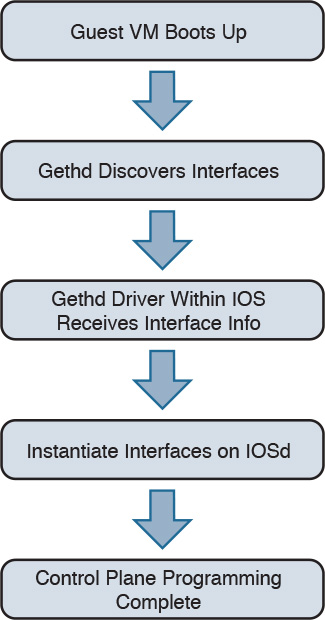
Figure 4-3 CSR 1000V Initialization Sequence
gethd is an important process that handles a variety of interface management functions, including interface removal/addition. It is an important part of the virtualized I/O used in CSR.
CSR 1000V Data Plane Architecture
Originally, IOS XE QFP data plane design consisted of four components: client, driver, QFP microcode (uCode), and crypto assist ASIC. Different ASR 1000 platforms package these components differently, but in general the four components are the same across platforms. CSR 1000V leverages the same client, driver, and uCode to support a multithread-capable packet processing data plane, with the exception of the crypto assist ASIC.
Figure 4-4 illustrates the CSR 1000V data plane architecture. The HW threads mentioned in the figure are packet processing engine (PPE) threads. The terms HW and PPE can be used interchangeably.
)
Figure 4-4 CSR 1000V Data Plane Architecture
The following is an overview of the three main components that make up the packet-processing data plane for CSR:
Client—The Client is software that ties together the control plane and the data plane. It is a collection of software modules that transform control plane information into various data plane forwarding databases and data structure updates. It is also responsible for updating the control plane with statistics from the data plane. It allocates and manages the resources of the uCode, including data structures in resource memory. The QFP Client is also responsible for restarting the QFP process in the event of failure. The Client provides a platform API layer that logically sits between IOSd and the uCode implementing the corresponding features. The Client API is called from FMAN-FP and then communicates with the uCode via both Interprocess Communicator (IPC) and shared memory interfaces provided by the Driver. Within the Client, feature processing support can be broken down into functional blocks known as Execution Agents (EA) and Resource Managers (RM). RMs are responsible for managing physical and logical objects, which are shared resources. An example of a physical object manager is the TCAM-RM, which manages allocation of TCAM resources, and an example of a logical object manager is the UIDB-RM, which manages the micro Interface Descriptor Block (uIDB) objects used to represent various forms of interfaces. The data plane (uCode) uses uIDB objects to see the logical interfaces.
Driver—The Driver is a software layer that enables software components to communicate with the hardware. It glues the software components to the hardware. The Driver is made up of libraries, processes, and infrastructure that are responsible for initialization, access, error detection, and error recovery. The Driver has hardware abstraction layering known as the Device Object (devobj) Model that allows it to support different QFP ASICs. Below the devobj API are implementations of various emulation and adaptation layers. In addition to the emulation and adaptation layers required to support the RMs listed in the Client section, the Driver is also responsible for coordinating memory access and IPC messaging between various QFP control plane software components and the QFP data plane packet processing uCode. The driver is completely segregated from the IOS code in an XE architecture, and this makes XE a very robust and flexible software architecture that offers complete separation of the control and data planes.
QFP uCode (packet processing)—The uCode is where all the feature packet processing occurs. The uCode runs as a single process in the same VM/container as the Client and the Driver processes. IOSd initiates a packet process request through FMAN-FP. This request is then driven by the Client and the Driver interacting with the uCode to control the PPE behavior. The QFP uCode is broken up into four main components: Feature Code, Infrastructure, Platform Abstraction Layer (PAL), and Hardware Abstraction Layer (HAL). The PAL and HAL are essentially glue for the portability of software features to different hardware platforms. Originally, the PAL and HAL were designed for Cisco forwarding ASICs, such as QFP. In order for uCode software to run on top of x86 in a Linux environment, a new PAL layer is needed to support the specifics of the CSR 1000V platform. In addition, a new HAL is introduced for running QFP software on top of x86 in a Linux environment.
The intention is for the CSR 1000V data plane to leverage as much of the existing QFP code base as possible to produce a full-featured software data plane capable of leveraging the processing capacity and virtualization capabilities of modern multicore CPUs. One way to minimize changes to the existing QFP software code base is to emulate QFP hardware ASIC in such a way that the existing Client, Driver, and QFP uCode are not aware that they are running on a non-QFP platform. However, due to the complexity of QFP hardware and the differences in platform requirements, a pure emulation is impractical. There are some cases where we choose to emulate hardware because doing so is the straightforward approach for code leverage. In other cases, it is best to replace the corresponding functionality with an implementation that is compatible at an API level but may be a completely different algorithmic implementation.
CSR 1000V Software Crypto Engine
Cisco router platforms are designed to run IOS with hardware acceleration for crypto operations. Like other ASR 1000 platforms, the ASR 1001 includes a crypto acceleration engine on board to deliver crypto offload and to increase encryption performance. In this environment, the main processor performing the data path processing is offloaded from the computing-intensive crypto operations. Once the crypto offload engine completes the encrypt/decrypt operation, it generates an interrupt to indicate that the packet should be reinserted back into the forwarding path.
The CSR 1000V runs completely on general-purpose CPUs without an offload engine; therefore, the software implementation of the IPsec/crypto feature path is needed to support the encryption function. To that end, the CSR 1000V includes a software crypto engine that uses low-level cryptographic operations for encrypting and decrypting traffic. The software crypto engine is presented to the IOS as a slower crypto engine. One thing to note is the software crypto engine runs as an independent process within the CSR 1000V, and it therefore may run as a parallel process in a multicore environment. To improve the crypto performance of the CSR 1000V software router, the crypto data path is implemented to take advantage of the latest Advanced Encryption Standard (AES) crypto instruction set from Intel (AES-NI) for encryption/decryption operations.
The newer Intel processors, such as the Xeon Westmere-EP family and mobile Sandy Bridge family, provide instruction sets for enhancing Advanced Encryption Standard (AES-NI) cryptographic operations performance. These instructions are included in the CSR 1000V crypto library, along with other cryptographic and hash algorithms for low-level crypto operations. The crypto library is used by the software crypto engine as well as by other subsystems within IOS that require cryptographic operations. The inclusion of Intel’s crypto instruction set allows the CSR 1000V to take advantage of the latest Intel CPUs for encryption and decryption operations in the data path.
Life of a Packet on a CSR 1000V: The Data Plane
Before we get into the details of packet flow for the CSR 1000V, it is important to understand the drivers that make it possible for the CSR VM to talk to physical devices and other software modules. These drivers act as software glue, relaying a packet to and from the physical wire. We have touched on the different hypervisors that enable the CSR VM to work on various x86 architectures. Here we discuss packet flow to and from a CSR VM.
Figure 4-5 shows the virtualization layers of a CSR 1000V VM.
)
Figure 4-5 CSR VM Layers
From Figure 4-5, you can see that the hypervisor presents a virtual NIC to its guest VM by using a driver. This driver can either be a para-virtualized driver (for example, VMXNET3) or a real/emulated driver (for example, e1000). Para-virtualized drivers are native to hypervisors and perform much better than emulated drivers such as the e1000. Hypervisors support emulated drivers because they are required for full virtualization. Recall from Chapter 1, “Introduction to Cloud,” that in full virtualization, guest operating systems do not require any support from the hypervisor kernel and run as though on real hardware. Therefore, support for emulated drivers is required. However, the performance of emulated drivers is much lower than that of para-virtualized drivers. The CSR VM supports para-virtualized drivers only.
Netmap I/O
Netmap is an open-source I/O infrastructure package that enables the CSR VM to get rid of the multiple software layers in the traditional Linux networking stack I/O model. This results in faster I/O. Understanding the Netmap I/O model will help you better understand packet flow to and from a CSR VM. This section provides an overview of the Netmap I/O model and compares it with a Linux I/O model. It is important to understand the I/O model before drilling down to packet flow.
Netmap is designed to strip down software layers and get the frame from the wire to the data plane process in user space as quickly as possible. Netmap achieves this through the four building blocks of its I/O architecture:
Thin I/O stack—Netmap bypasses the Linux networking stack to reduce overhead. Since the CSR data plane runs in the user space, when it wants an I/O architecture to deliver receive (Rx) frames from the NIC to the user space (data plane) and transmit (Tx) frames from the data plane to the NIC, it leverages Netmap’s thin I/O stack.
Zero copy—Netmap maps all memory from rings (pool of memory buffers) in a way that makes them directly accessible in the data plane (user space). Hence there is no copy involved in getting the information to the user space. Preventing a copy operation saves a lot of time in an I/O model, and Netmap’s zero-copy model is very effective at increasing performance compared to a traditional Linux I/O model.
Simple synchronization—The synchronization mechanism in Netmap is extremely simple. When you have the Rx packets on the ring, Netmap updates the count of new frames on the ring and wakes up threads that are sleeping to process the frames. On the Tx side, the write cursor is updated as a signal to announce the arrival of new frames on the Tx ring. Netmap then flushes the Tx ring.
Minimal ring manipulation—In the Netmap I/O architecture, the ring is sized such that the producer accesses the ring from the head end, while the consumer accesses it from the tail. (Producer and consumer are terms associated with the process that tries to initiate the I/O process [producer] and a process that gets affected in trying to serve the producer [consumer].) The access to the ring is allowed simultaneously for the producer and the consumer. In a regular Linux I/O scenario, you would have to wait for the host to fill up the ring with pointers to buffers. When the ring is being serviced, Linux detaches the buffers from the ring and then replenishes the ring with new pointers.
An overview of the layers of software involved in building a CSR 1000V VM is illustrated previously in Figure 4-5. Figure 4-6 compares the Linux I/O model with the Netmap I/O model.
)
Figure 4-6 Linux Versus Netmap I/O Comparison
Packet Flow
There are three major data plane components:
Rx thread
Tx thread
HQF (Hierarchical Queuing Framework) thread
All these components run on a single process within the QFP process umbrella. Multiple PPE threads serve requests within this QFP process. The following sections discuss the flow.
Device Initialization Flow
The following events take place to get the NIC (or vNIC, in a para-virtualized environment) ready for operation:
During boot-up, the platform code within IOSd discovers all Linux network interfaces. The platform code then maps these Linux interfaces—eth0, eth1, and so on—to Gig0, Gig1, and so on. After talking to the kernel, platform code sets up the interface state (up or down), sets the MTU, sets the ring size, and sets the MAC address.
The FMAN process creates the FMAN interfaces and then reaches out to the QFP client process to initialize the data-plane interface.
After the QFP process receives the initialization message from the Client process to create an interface, the QFP process then initializes an interface called micro-interface descriptor block (uIDB) in the data plane.
After the uIDB is created in the QFP process, the FMAN process binds this uIDB to the network interface name.
The component of the data-plane process responsible for interacting with the kernel now has to make sure that the interface created with the QFP process is registered and enabled within the Netmap component of the kernel.
With the new interfaces registered, the Netmap component communicates with the virtual NIC driver to initialize the physical NIC.
The vNIC driver opens the NIC, initiates the rings, and makes the NIC ready for operation.
TX Flow
The following events take place when there is a packet to be transmitted (Tx) by the CSR onto the wire:
The HQF thread detects that there are packets to be sent.
The HQF thread checks congestion on the transmit interface and checks the interface states.
If the transmit interface is not congested, HQF sends the frame. HQF can also wait to accumulate more frames, batch them, and then send them out.
The platform code locates the next available slot in the Tx ring and copies the frame from the source buffer into the Netmap buffer for transmission.
The platform code flushes the Tx ring.
Netmap forwards the flushed frames to the vNIC driver.
The vNIC driver initializes the NIC Tx slots.
The vNIC driver writes onto the Tx registers.
The vNIC driver cleans up the Tx ring of done slots.
The vNIC sends the frame on the wire and generates a notification on completion.
RX Flow
The following events occur whenever a CSR receives a packet to be processed:
The Rx thread (the thread that receives frames from the QFP process) issues a poll system call to wait for the new Rx frames.
When a new frame arrives, the NIC (or vNIC, in this case) accesses the vNIC Rx ring to get a pointer to the next Netmap buffers.
The vNIC puts the frame onto the next Netmap buffers.
The vNIC generates an Rx interrupt.
The Netmap Rx interrupt service routine runs the Rx threads.
The vNIC driver finds the new frame and creates memory buffers for it.
The Rx thread pushes the frame to the PPE thread for processing.
Figure 4-7 illustrates packet flow between different XE processes.
)
Figure 4-7 Flowchart for Packet Flow
Unicast Traffic Packet Flow
The Tx and Rx flows in Figure 4-7 detail how a packet is transmitted from the NIC (or vNIC, in a para-virtualized driver) to the QFP process. Now we can look at how the QFP process handles the packet after it gets it. The following steps examine a unicast IPv4 packet flow:
The QFP process receives the frame from the Netmap Rx and stores it in Global Packet Memory (GPM).
The Dispatcher copies the packet header from the GPM and looks for free PPE to assign. The packet remains in the GPM while it is being processed by the PPEs.
The Dispatcher assigns a free PPE thread to process the feature on the packet.
PPE threads process the packet and gather the packets. The gather process copies the packets into B4Q memory and sends the HQF thread a notification that there is a new packet in the B4Q memory.
HQF sends the packet by copying it from B4Q into the Netmap Tx ring, and then releases the B4Q buffer.
The Ethernet driver sends the frame and frees the Tx ring once the packet has been sent out.
Multicast IPsec packets are recycled from the HQF thread back to the in/out processing of the PPE threads.
Figure 4-8 illustrates the packet flow in the QFP process.
)
Figure 4-8 CSR 1000V Packet Flow in the QFP Process
Installing the CSR 1000V on a VMware Hypervisor
The process for installing the CSR 1000V on a VMware hypervisor has two phases:
Bring up the VM with the CSR 1000V on ESXi.
Connect the VNIC with the CSR 1000V.
These phases can be subdivided into the step-by-step procedures described in the following sections. To learn about automated provisioning using the BDEO (build, deploy, execute OVF), see Chapter 7, “CSR in the SDN Framework.”
The following steps assume ESXi is already installed. Please refer to the VMware ESXi installation guide for setting up the ESXi if it is not already installed.
Bringing Up the VM with the CSR 1000V on ESXi
Assuming ESXi is already installed, you can now follow these steps in the first phase of installing the CSR 1000V:
Step 1. Deploy the OVF template:
Download the OVF template from software.cisco.com and select CSR 1000V software.
Log on to the vSphere client, as shown in Figure 4-9.
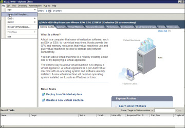
Figure 4-9 Installing the OVF Template for the CSR 1000V
Upload the CSR OVF file you downloaded from cisco.com as shown in Figure 4-9.
Select File, Deploy OVF Template, as shown in Figure 4-9.
Step 2. Upload the CSR OVF file as shown in Figure 4-10.
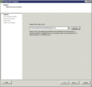
Figure 4-10 Deploying the OVF Template: Selecting the Source
Step 3. When the OVA upload is done, verify the OVF template details on the screen shown in Figure 4-11.
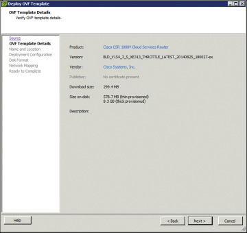
Figure 4-11 Deploying the OVF Template: Verifying the Template Details
The release information, product, size, and so on are received from the metadata. Follow the directions for creating the VM.
Complete the following deployment configuration, disk formatting, and network mapping screens, as shown in Figures 4-12 through 4-16:
As shown in Figure 4-12, select the hardware profile: Small, Medium, or Large vCPU and RAM, based on the deployment considerations. Refer to the hypervisor documentation for the exact small, medium, and large VM configurations. (You can change this configuration for memory even after the CSR 1000V is brought up.)
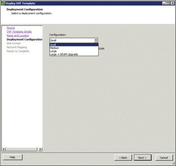
Figure 4-12 Deploying the OVF Template: Selecting the System Memory Profile for CSR 1000V
Select the appropriate type of disk formatting (see Figure 4-13), and then click Next:
Thick Provision Lazy Zeroed—With this option, a virtual disk is created with the amount of disk space it has asked for. However, the disk is not cleaned during virtual disk creation. It is cleaned only when you create the first VM on it.
Thick Provision Eager Zeroed—With this option, a virtual disk is created with the amount of disk space it has asked for. However, the disk is cleaned during virtual disk creation.
Thin Provision—Choose this option to save space. Initially, the space allocated to a thin disk is less. However, the virtual disk keeps growing as memory requirements grow.
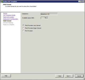
Figure 4-13 Deploying the OVF Template: Choosing the Disk Provisioning Format
On the screen shown in Figure 4-14, specify network mapping of the source networks (GigabitEthernet) to the destination networks (VM Network by default) mapping allocation.
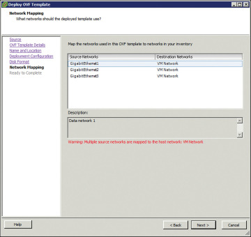
Figure 4-14 Deploying the OVF Template: Network Mapping
Look over the summary of the deployed CSR 1000V configuration, as shown in Figure 4-15, and click Finish.
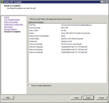
Figure 4-15 Deploying the OVF Template: Checking the Settings
Step 4. When the deployment of the CSR 1000V is complete, boot the router by selecting the VGA console from the GRUB menu on the Console tab shown in Figure 4-16.
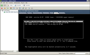
Figure 4-16 CSR 1000V Console Tab
Step 5. At the router prompt, enter platform console serial, as shown in Figure 4-17. (This command causes the VM to send console information on the serial port from ESXi in the later steps.)
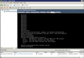
Figure 4-17 CSR 1000V Command Prompt
Step 6. To add the serial port for console access, access the vCenter web client and select Virtual Hardware, Network Adaptor, Serial Port, as shown in Figure 4-18.
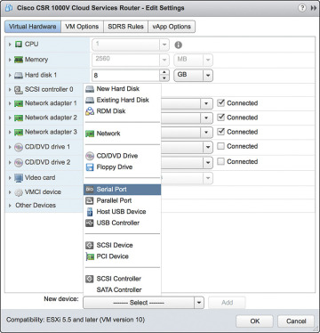
Figure 4-18 VM Access from the vCenter Web Client
Step 7. Shut down the guest OS as shown in Figure 4-19. (Note that this serial port will be used for terminal access to the CSR.)
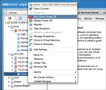
Figure 4-19 Configuring the Serial Interface: Shutting Down the Router
Step 8. Select Add New Device, New Serial Port and provide the IP address and terminal port details to access the CSR, as shown in Figure 4-20.
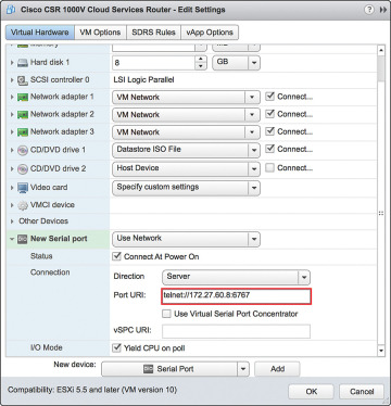
Figure 4-20 Configuring the Serial Interface: Setting the Telnet Address
Step 9. Go to vCenter and select Setting, Security Profile. Edit security configuration ports 23 and 1024 as shown in Figure 4-21. This is needed because by default ESXi blocks console access.
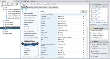
Figure 4-21 Configuring the Serial Interface: Firewall Settings
Step 10. Enable ports 23 and 1024 as shown in Figure 4-22.
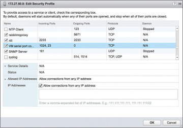
Figure 4-22 Configuring the Serial Interface: Security Profile Detail
Step 11. Use Telnet to verify the access from the PC. (It’s a good practice to use SSH for accessing the CSR VM; however, for the sake of simplicity, this example shows Telnet access setup.) The EXSi hypervisor defaults the network connections to the VM Network virtual switch connection. The network adapters are mapped to CSR interfaces. For example, GigabitEthernet1 is mapped to Network adapter 1, and so on. You can verify this by comparing the MAC address as illustrated in Figure 4-23.
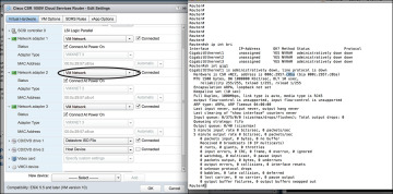
Figure 4-23 CSR 1000V Telnet Access Screen
Step 12. To remap the network adapters to corresponding vNICs, you should perform the following steps. From the vSphere client in the Edit Settings window, select New Device Add, Networking and add vNICs to the CSR as assigned interfaces (from the vCenter web client), as shown in Figures 4-24 through 4-27. (Allow all VLANs and create a bridgeForVNIC1 label for this connection.)
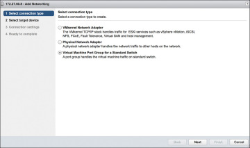
Figure 4-24 vNICs and the CSR 1000V: Selecting the Connection Type
Select the new vNIC, as shown in Figure 4-25, to create a new standard switch name.
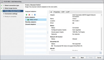
Figure 4-25 vNICs and the CSR 1000V: Creating a Standard Switch
Add VLANs and the network label assigned for the vNIC, as shown in Figure 4-26.
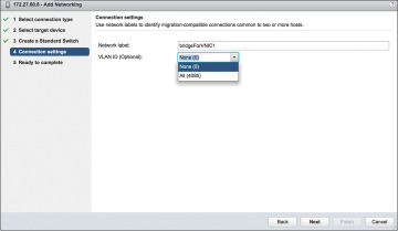
Figure 4-26 vNICs and the CSR 1000V: Setting the Connection Settings
Complete the configuration of the vNIC with a VLAN and label attachment that can be referenced in a vSwitch. Click Finish to complete this step, as shown in Figure 4-27.
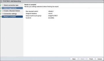
Figure 4-27 vNICs and the CSR 1000V: Completing the Configuration
Step 13. Go to the vSphere web client and select Virtual Machine, Network Adapter. In the Networking tab, look for the new bridgeForVNIC1 label you created earlier, as shown in Figure 4-28. You should note that this label acts as mapping between the CSR interface and the vNIC.
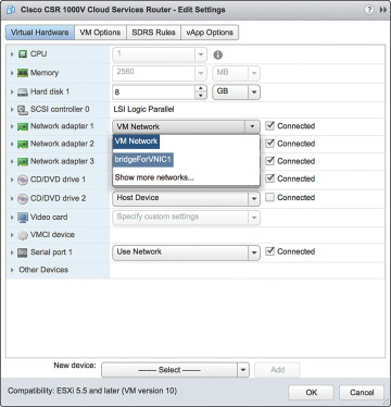
Figure 4-28 vNICs and the CSR 1000V: Editing the Settings
Repeat Steps 12 and 13 to remap additional network adapters to vNICs available to the CSR.
To map the network adapter to the vNIC created, select the vNIC label created in the previous step. The CSR 1000V is now configured and connected to the physical NIC, as shown in Figure 4-29.
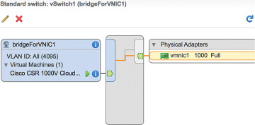
Figure 4-29 vNICs and the CSR 1000V: Interface Summary Screen
)
)
)
)
)
)
)
)
)
)
)
)
)
)
)
)
)
)
)
)
)
Installing the CSR 1000V on a KVM Hypervisor
The process for installing the CSR 1000V on a KVM hypervisor has two phases:
Bring up the VM with the CSR 1000V on ESXi.
Connect the vNIC with the CSR 1000V.
Bring Up the CSR 1000V as a Guest
Follow these steps to update essential packages on a Linux managed server so it can work as a type 1 hypervisor and run a CSR 1000V VM:
Step 1. Install the VM packages virt-manager, qemu-kvm, and bridge-utils like this:
apt-get install virt-manager
apt-get install qemu-kvm

apt-get install bridge-utils
or like this:
yum install virt-manager
yum install qemu-kvm

yum install bridge-utils
Figure 4-30 shows the installation of packages required for CSR creation.
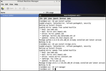
Figure 4-30 Package Installation on a KVM Hypervisor
Step 2. Launch Virtual Machine Manager, which is the front end to KVM/QEMU that allows installation and management of CSR VMs, by selecting Application, System, Virtual Machine Manager.
Click the Create a New Virtual Machine icon, and the dialog shown in Figure 4-31 appears. Click the Forward button.
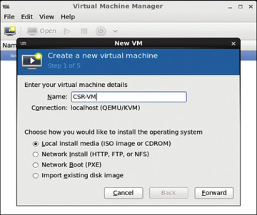
Figure 4-31 Creating a Guest VM
Step 3. Load the ISO image (which you download from software.cisco.com ) for the CSR 1000V, as shown in Figure 4-32. Click the Forward button.
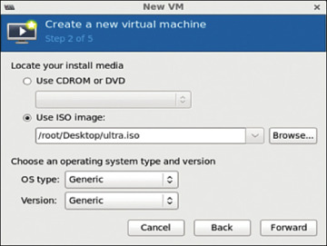
Figure 4-32 ISO Image Bootup for the CSR 1000V
Step 4. Allocate hardware resources for the guest VM as shown in Figure 4-33. (Refer to Table 2-2 in Chapter 2 for further allocation information.) Click Forward.
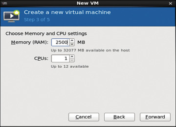
Figure 4-33 Choosing Memory and CPU Settings
Step 5. Select hardware resources, as shown in Figure 4-34, and click Forward.
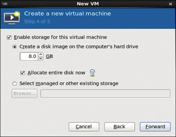
Figure 4-34 Selecting Hardware Resources
Step 6. Look over the hardware resources summary (see Figure 4-35) and make any changes needed. Click Finish.
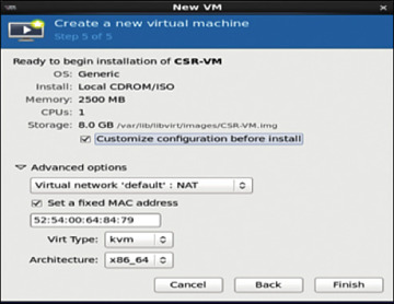
Figure 4-35 Resources Summary Snapshot
Step 7. To apply changes for the guest VM, select Application, System, Virtual Machine Manager and highlight the CSR installed in the VMM. Then click the Show Virtual Hardware Details tab and click the Add Hardware button, as shown in Figure 4-36.
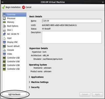
Figure 4-36 Applying Hardware VM Changes
Step 8. To create serial connection access for console access, select Serial, and then select TCP for Device Type and provide the telnet information, as shown in Figure 4-37.
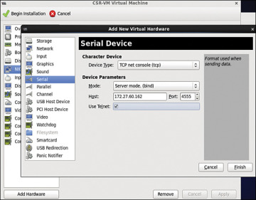
Figure 4-37 Creating the Serial Interface
Step 9. In the Virtual Machine Manager, highlight the guest VM and shut it down (if it is not down already). (See Figure 4-38.)
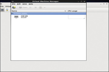
Figure 4-38 Shutting Down the Guest VM
The guest VM goes down, as shown in Figure 4-39.
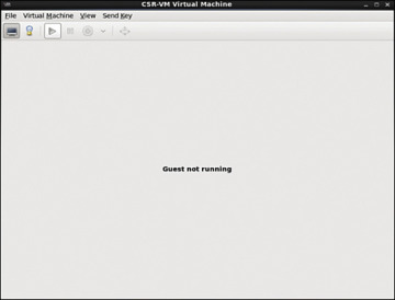
Figure 4-39 Shutdown of the Guest VM
Step 10. Access the router from the console, as shown in Figure 4-40. Make sure the VM is powered up before you try to access it.
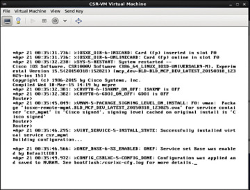
Figure 4-40 Console Access to the KVM
Step 11. Use the serial interface command for telnet access: platform console serial and write mem, as shown in Figure 4-41.
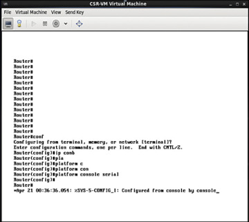
Figure 4-41 Router Console for Telnet Access
Step 12. Access the CSR 1000V via the telnet, as shown in Figure 4-42.
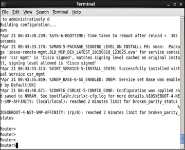
Figure 4-42 Telnet Connection to the CSR 1000V
Step 13. Ensure that your virtual machine is shut down, and then start vNIC provisioning by selecting Show Virtual Hardware Details, NIC, as shown in Figure 4-43.
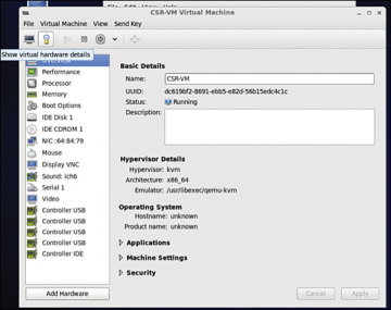
Figure 4-43 Accessing CSR 1000V Network Settings
Step 14. In the Virtual Machine Manager, select virtio as the device model (see Figure 4-44) because it is the para-virtualized driver in Linux. Using virtio is the best way to exploit the underlying kernel for I/O virtualization. It provides an efficient abstraction for hypervisors and a common set of I/O drivers.
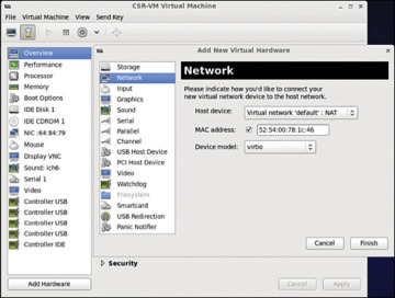
Figure 4-44 Selecting CSR 1000V Network Settings
Select the virtual network with NAT to tie all VMs in the same bridge domain and NAT it to the outgoing physical interface (see Figure 4-45). Attach the other NIC to the bridge tap.
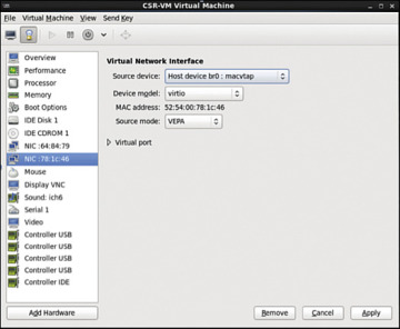
Figure 4-45 CSR 1000V NIC Settings
In KVM, macvtap is a combination of the macvlan driver and a Tap device. Here the function of the macvlan driver is to create virtual interfaces and map virtual interfaces to physical network interfaces. A unique MAC address identifies each virtual interface to the physical interface. A TAP interface is a software only interface that exists only in the kernel. You use Tap interfaces to enable user-space networking and allow passing of datagrams directly between VMs instead of sending datagrams to and from a physical interface. The macvtap interface combines these two functions together (see Figure 4-46).
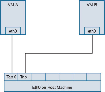
Figure 4-46 macvtap Diagram
Step 15. Configure the mapping of the vNIC to the physical interface:
Access the directory /etc/network/interfaces/ifcfg-br0 on the Ubuntu host and view the bridge type (see Figure 4-47).
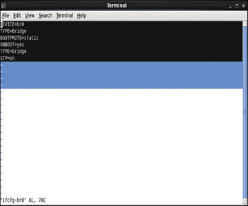
Figure 4-47 Bridge Configuration File Output
Access the directory /etc/network/interfaces/ifcfg-eth4 and configure the vNIC to be in the same bridge type, BR0 (see Figure 4-48).
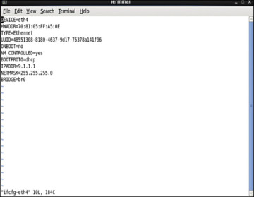
Figure 4-48 Interface Configuration File Output
To configure the spanning tree mode to promiscuous, use this:
auto eth4
iface eth4 inet manual

up ip address add 0/0 dev $IFACE

up ip link set $IFACE up

up ip link set $IFACE promisc on
Alternatively, access the file /etc/network/interfaces/ifcfg-eth4 and type this:
PROMISC=yes
This method provides persistent configuration settings for ifcfg-eth4.
Step 16. In the Virtual Machine Manager, select Show Virtual Hardware Details.
)
)
)
)
)
)
)
)
)
)
)
)
)
)
)
)
)
)
)
)
Performance Tuning of the CSR 1000V
To improve performance of a guest VM in a hypervisor environment, you improve availability of the I/O and other hardware resources through para-virtualization. Para-virtualization allows for a kernel to present a software interface to a guest VM that is similar but not identical to that of the underlying hardware, thereby improving the VM performance. If you want to tune the performance further, you need to look at two components:
Hypervisor scheduling
CPU pining
This section reviews the common tuning practices for an ESXi host. The scheduler for ESXi is responsible for vCPU, IRQ (interrupt requests), and I/O threads. To provide equal treatment to all guest VMs, the scheduler provides allocation of equal resources of vCPU threads for scheduling. Note that you can relax coscheduling of threads to avoid synchronization latency.
To tweak the scheduling and resource allocation details, you must access the VM setting using vSphere client and follow these steps:
In the vSphere client inventory, right-click the virtual machine and select Edit Settings.
Click the Resources tab and select CPU.
Allocate the CPU capacity for this virtual machine.
The Processor Affinity setting (CPU pining) restricts VMs to a particular set of cores by defining the affinity set. The scheduling algorithm aligns with process affinity for assigning the resources used for the tasks. Figure 4-49 assumes two tasks: Task 1 and Task 2. Task 1 has affinity to processor 1 and is using it. When Task 2 needs a resource, the scheduler uses a second processor. Task 2 then acquires affinity with the second processor.
)
Figure 4-49 CPU Pining
To tweak these settings, access the vSphere client and follow these steps:
In the vSphere client inventory panel, select a virtual machine and select Edit Settings.
Select the Resources tab and select Advanced CPU.
Click the Run on Processor(s) button.
You achieve CPU pining in KVM by issuing the following command:
sudo virsh vcpupin test 0 6
Hyperthreading by definition allows a single physical core to have two logical cores; that is, a single core can execute two threads at a given time. Each process from the guest VM can be split into multiple threads to a logical CPU, and the CPU can handle multiple threads of independent tasks. The main function of hyperthreading is to increase the number of tasks in the pipeline by creating parallel pipelines. By tweaking the process affinity option, you can restrict VMs to a particular set of cores and unhook the VM from processor scheduling. Most of the hypervisors use BIOS settings to modify the hyperthreading feature.
For predictable performance, the following best practices are recommended:
Ensure that hyperthreading is turned off.
Use CPU pining to allow the guest VMs to dedicate one or more physical hardware CPUs for processing.
For CSR 1000V performance optimization, it is important to understand the concept of DirectPath I/O and SR-IOV (single root I/O virtualization). These are driver virtualization and are beneficial for achieving very high packet rates with low latency. In DirectPath I/O, you can map only one physical function to one virtual machine. SR-IOV allows an admin to share a single physical device, so that multiple virtual machines can connect directly to the physical function.
These features are supported in all hypervisors, and it is important to understand the settings on the hypervisor deployed in order to optimize guest VM performance with features used on the hypervisor.
Summary
Now that you’ve read this chapter, you should have an understanding of the CSR 1000V data plane architecture, as well as packet flow. You should also have an understanding of the steps for bringing up a CSR 1000V on ESXi and KVM hypervisors.